Influence of LED Nonlinearity on Orthogonal Frequency Division Multiplexing Based Visible Communication System
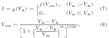
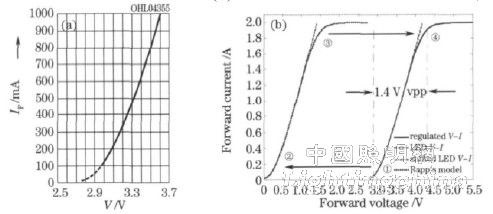
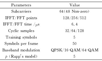
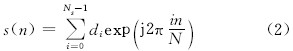
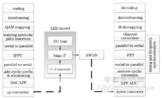
1 Introduction Light-emitting diodes (LEDs) have become promising lighting devices due to their energy saving, environmental protection, high brightness and long service life. The LED has both extremely fast response speed and wide modulation bandwidth, and it has the potential to transmit data while meeting the lighting requirements, thus forming a visible light communication system (VLC). The visible light band used by VLC does not require frequency authorization, the implementation cost is very low, communication security and spatial reusability are high, which makes VLC attract more and more attention worldwide. Orthogonal Frequency Division Multiplexing (OFDM) has extremely high spectral efficiency, low bit rate and cyclic prefix structure. It is very suitable for solving problems such as dispersion and polarization mode dispersion in optical fiber communication. In free space optical communication. OFDM has also been proposed to solve problems such as scattering in the atmospheric channel. In LED-based VLC systems, the modulation bandwidth is extended from a few megahertz to a dozen megahertz by filtering out the slower response fluorescence components. On this basis, OFDM is applied to VLC to combat multipath effects and achieve high speed. Data dissemination and communication. OFDM is very sensitive to frequency and phase noise, while higher time-domain peak-to-average power ratio (PAPR) requires high linearity of the amplifier. In VLC systems using discrete multi-frequency (DMT) and OFDM, LEDs are considered to be the main source of nonlinearity. 1) The IV characteristic of the LED itself is non-linear; 2) To ensure the safe operation of the LED and the limited word length effect of the digital-to-analog converter, it is necessary to soft-cut or hard-cut the modulated signal to limit the modulation power. , thus introducing more nonlinear problems. Therefore, it is necessary to analyze the nonlinearity of the LED. Elgala et al., referring to the solid-state power amplifier model of Rapp, proposed a soft-cutting model for LED modulation current, and the results show that soft-cutting performance is better than hard-cutting. However, there are still problems in the practical application of this method for modeling and analyzing different types of LEDs: the acquisition and measurement of the IV data exceeding the maximum inrush current of the LED required by the model is difficult, and the physical meaning is not clear enough. Based on this, an effective method for constructing a nonlinear model of LED with bidirectional saturation characteristics based on partial IV data is proposed. Based on the modeling results, the effects of LED nonlinearity on OFDM system are analyzed and analyzed. The results are discussed. 2 OFDM system model Decoding a set of frequency orthogonal subcarriers with a set of parallel complex frequency domain digital baseband symbols to form a time domain expression of the OFDM symbol is (1) is formally equivalent to The inverse discrete Fourier transform with the Ns point M-QAM complex frequency domain symbol is shown, so that fast and efficient OFDM signal modulation can be realized by the Fast Fourier Transform (IFFT) algorithm. At the receiving end, data synchronization of all subcarrier channels can be completed by Ns point fast Fourier transform (FFT) through time domain and frequency domain synchronization and signal sampling. Figure 1 shows the transmission and reception process of a visible light OFDM system. In an intensity modulated VLC system, an additive white Gaussian (AWGN) channel can be used as a channel model, including background optical noise, receiver shot noise, thermal noise, and the like. Intensity modulation requires that the transmitted light intensity cannot be negative, so the LED DC bias point needs to be added to the OFDM system channel model. In an optical OFDM system, the mapping of the frequency domain symbols on the subcarriers to the conjugate symmetry is usually performed, so that the OFDM baseband time domain signal after the IFFT is a real number, which facilitates the direct transmission of the baseband signal. Taking the 48-subcarrier OFDM system as an example, as shown in Table 1, D1, D2, ... represent the complex frequency domain symbols of the corresponding subcarrier channels, and D1*, D2*, ... are their complex conjugates. Half of the factor carriers carry redundant information at the expense of a 1/2 reduction in bandwidth efficiency. Figure 1 OFDM-VLC system transmission and reception flow chart Table 1: Frequency domain symbol mapping of 48 subcarrier channels with conjugate symmetry 3 Nonlinear model of LED When the parasitic parameters such as series and parallel resistance exist, and the influence of LED heating effect is not considered, the Shockley equation representing the characteristic of LEDI-V is Where Rs is the parasitic series resistance, Rp is the parasitic shunt resistance, k is the Boltzmann constant, T is the LED junction temperature; nideal is the idealized factor for the LED, and for GaN/GaInN blue LEDs, the value is about 7.0; Is For the constants associated with LED materials and structures, there is a dimension of current. When Rp approaches infinity, equation (3) can be expressed as Based on this, the LED nonlinear modeling process can be expressed as follows: 1) Based on the partial IV data provided or measured by the LED manufacturer. Define Vth as the turn-on voltage of the LED. First, shift the IV curve in the opposite direction of the voltage axis Vth on the plane. The turn-on voltage coincides with the origin of the coordinate. The voltage after translation is expressed as Vshift. Fit to I-Vshift as follows. 2) Substituting the maximum inrush current Imax into the fitting result of (5), the maximum forward saturation voltage Vsat=Vshift(Imax) allowed by the LED is obtained. Referring to the solid-state power amplifier model such as Rapp, with Vsat as its maximum output voltage, there is Where Vrout maintains a linear relationship with the input voltage Vshift amplitude, and the portion of the amplitude greater than Vsat will be softly chopped. The degree of rounding of the top is determined by the parameter p. The larger the value, the worse the smoothness, and vice versa. 3) If the I-Vshift characteristic of the LED is represented by the function I=f(v), the voltage after the cutting is shifted to the positive direction of the voltage axis Vth to obtain the final modeling result, and the IV characteristic can be expressed as Where Vin is the modulation voltage of the LED. Through the above process, the LEDI-V curve exhibits a bidirectional saturation characteristic at less than the turn-on voltage Vth and beyond the maximum surge modulation voltage Vsat+Vth. 4 Simulation and analysis of LED nonlinear effects The typical OSRAM LUW CP7P high-power white LED is represented by the above method, and the process is shown in Figure 2(b). The key steps are as follows: 1) The IV characteristics of the LED provided by the manufacturer are shown in Fig. 2(a), the turn-on voltage Vth=2.77V, the maximum DC operating current 1A, the maximum inrush current Imax=2A, and the rated power 1W. At high forward voltages, LED devices can only operate in a pulsed manner, and this is not a typical application for such LEDs for illumination, so IV data with a modulation current in the range of 1 to 2 A is not directly given. The experimental measurement can be performed by the pulse method, or extrapolated using the fitting result of (5) in the modeling process. Figure 2 (a) OSRAM LUW CP7PLEDI-V characteristic curve; (b) LED nonlinear modeling process integrated with Rapp power amplifier model 2) Perform the steps in Section 3 to get Vsat=1.41V. Taking p=5 in the power amplifier model such as Rapp, the IV characteristics of the LED after modeling are shown in the solid line in Figure 2(b). Table 2 lists the key parameters used in the Monte Carlo simulation of OFDM system performance. In order to directly analyze the influence of the nonlinearity of the LED on the performance of the OFDM system, the simulation for the non-coded OFDM system will omit the coding and decoding, binary to multi-ary mapping, and interleaving and de-interleaving. Table 2 OFDM and LED simulation parameters 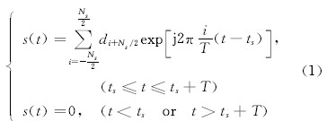

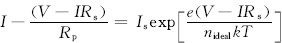 (3)
(3) 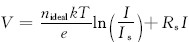 (4)
(4) 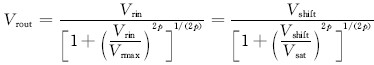 (6)
(6)