XY ・ CN bus power supply and communication system
The call system is one of the important monitoring systems in the hospital. A good call system can help patients get timely help, improve the efficiency of nurses, and more importantly, can record the nurses' working conditions and provide first-hand information for human resource management. At present, the most widely used calling system is the split-line calling system, which has the advantages of simple equipment and low cost, but its parallel structure has complicated wiring and single function. The wireless call system has the advantages of no wiring, convenient installation, and portability, but the equipment has high cost, single function, frequent battery replacement, poor communication penetration, and reliability is not guaranteed. This article takes the application of XY · CN bus in this system as the main line, and introduces the realization of the specific application scheme of XY · CN bus. 1 System scheme design 2 System equipment 2.1.2 Main functions ①Control the entire bus communication. The main controller realizes the network management of the nurse response processor and the doctor's responder through the master station bus control circuit centered on XYlO0, and the reporting and recording function of various control information. 2.2.2 Main functions ①Answer the intercom. After a patient calls, the nurse's LCD of the processor will display the patient's ward number, bed number and patient name, etc., and notify the nurse by voice; the nurse can talk to the called patient individually by pressing the answer key. The patient's details. When answering overtime, the controller automatically switches to the information display for audio and video calls. When it is necessary to notify the doctor for processing, call the doctor via phone slave. This process can also be automatically controlled by the host to call the doctor on duty when the professional doctor is absent, or to call the doctor through the host phone. 2.3.2 Main functions The room number and bed number of the calling patient are displayed through this display, and the nurse is also prompted by the voice engine. When the nurse is nursing in the ward, there is no need to return to the nurse's station. Through this information display, the patient's call information can be understood and processed accordingly. 2.4.2 Main functions ①Call intercom function. The patient presses the button to call the nurse. After the nurse responds, the patient can talk directly with the nurse. Conclusion Through this design, we have a deeper understanding of the structure and solution of the network control system completed by the XY · CN bus. The XY · CN bus is a field bus control system with a simple structure, powerful functions, and low cost.
UFO LED High Bay is round High Bay Lights with the driver on top of the fixture. Ufo High Bay Led is ideal for warehouse lighting and can be mounted.UFO LED High Bay is a UFO disc-shaped LED luminaire system which features a flat integral aluminum.Led Ufo High Bays is the impressive evolution of the warehouse light or high ceiling light. Small and compact. Ufo Led Lights Industrial Light`s power are 60W. 100W. 150W. 200W. its light color are White Light(WH) and Neutral White (NW). 150W Led Ufo High Bay is Widely used in supermarkets, convenience stores, gas stations, parking lots, warehouses, shops, high bays, low bays, street lights, hotels, motels, etc.
UFO LED High Bay Ufo High Bay Led,Led Ufo High Bays,Ufo Led Lights,150W Led Ufo High Bay Shenzhen Bbier Lighting Co., Ltd , https://www.chinabbier.com
1.1 System block diagram The first-level XY · CN bus completes the equipment management work within the jurisdiction of a nurse's duty room. The secondary XY · CN bus completes the information network recording of the nurse's response processor and the emergency call to the doctor.
1.2 Description of procedure ①The patient seeks help. The patient call is completed by calling the intercom. The XY · CN bus has a quick response function. The patient call will generate audio and video alarms on the nurse response processor within 80 ms, and indicate the patient's bed number and patient name And other information.
â‘¡The nurse responds to the treatment. After receiving the help, the nurse controls the audio telephone system connected with the patient, understands the help problem and carries the necessary items to deal with. After the help processing is completed, the nurse presses the key on the intercom or provides the IC card for identity recognition to complete the confirmation process for the main controller to record the processing process.
â‘¢The nurse calls the doctor. After the nurse performs identification through the IC card, he directly calls the professional doctor of the bed on the call intercom for emergency treatment, and can also complete calls to different doctors on the nurse answering processor.
â‘£ Generate process records. All the information is recorded by the host, and then the PC is used to extract the records through the USB port, and the management software of the host computer is used to organize and form a printed report to provide management basis for the manager. 
2.1 Main controller
2.1.1 Device block diagram The structure of the main controller is shown in Figure 2. It is mainly composed of communication chip XYl00, microcontroller, peripheral equipment, power management circuit, etc. 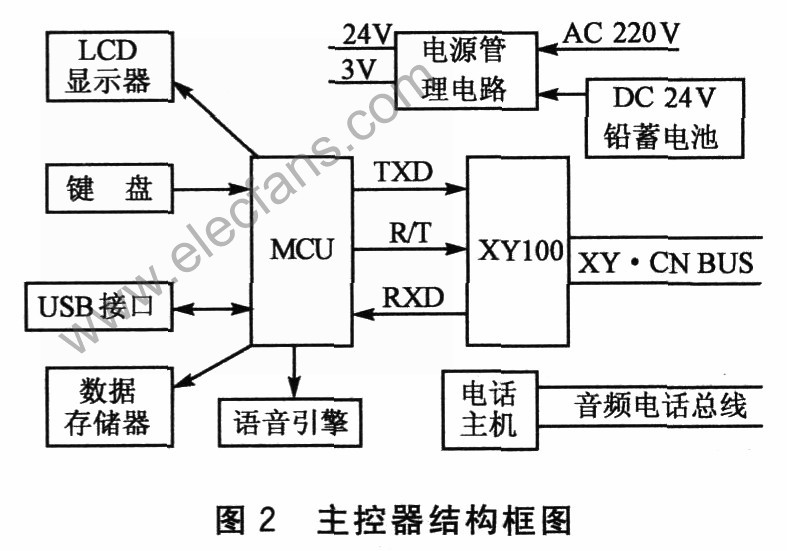
â‘¡System power supply. The power supply system of the main controller realizes the power supply function of the secondary bus system. During normal operation, the main controller takes power from the mains and charges the 24 V lead battery; after a power failure, the 24 V lead battery supplies power.
â‘¢Detect failure and alarm. Real-time detection of bus, backup power system failure, receiving its failure information and sound alarm.
2.1.3 Operation and installation As the host computer is located in the office or financial room, it is responsible for information exchange, processing, storage and statistics of the entire system, and generates management reports through the PC for human resource management as the basis for rewards and punishment of medical personnel. You can also set up a telephone communication interface on the device to handle emergency requests from nurses to doctors at night, and directly implement emergency phone calls to related doctors based on controller information.
2.2 Nurse response processor
2.2.1 Device block diagram The device structure is shown in Figure 3. The main circuit consists of XY001, XY100, MCU, telephone host, telephone extension, LCD display, keys and voice engine (W701). Radio frequency card module can also be installed if identity recognition is required. 
â‘¡ ID identification response. After the nurse receives the patient's call, the IC card is used to identify the identity and confirm that a nurse has been processed.
â‘¢ Report the record during the process. All operations upload the host through the bus to generate a complete record, which provides reliable management information for the hospital's formal management.
2.2.3 Operation and installation The device is located at the nurse station, manages all call intercoms under the nurse station, displays patient calls and handles call responses. The nurse receives the information confirmed by the call back through the intercom and completes the processing, and reports the processing information recorded by the main controller through the secondary bus. Provide telephone and bus power for its equipment.
2.3 Information display
2.3.1 Device block diagram The device structure is shown in Figure 4. The main device consists of XY001, MCU, LED display and telephone voice. 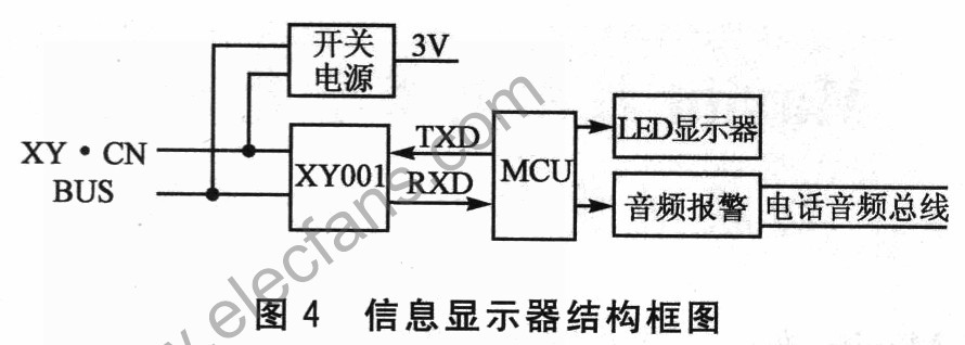
2.3.3 Operation and installation The device is located in the hospital corridor and displays the patient's call information for the nurse to quickly and continuously deal with the patient's help.
2.4 Call intercom
2.4.1 Device block diagram The structure of the call intercom is shown in Figure 5. The main device consists of XY001, MCU, buttons and LED. Radio frequency card modules can also be added to the responses that require identification. 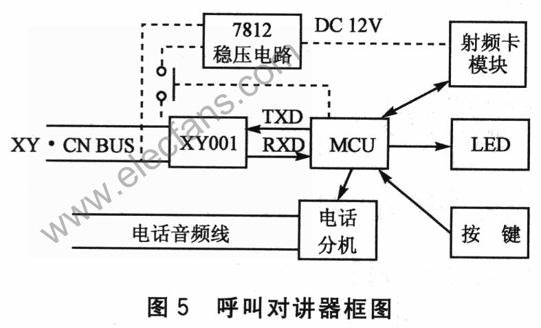
â‘¡ Response processing function. After the nurses have finished nursing, they press another button or insert an identity IC card to inform the main controller that the patient's call has been processed and a record is generated.
â‘¢Call the doctor urgently. You can also set the call doctor button on the call intercom with IC card, and the nurse will complete the call.
2.4.3 Operation and installation The device is located on the bedside of the patient. The patient can call for help by pressing the button. The nurse answers and talks on the nurse response processor. It is located in the doctor's clinic or office. When the doctor needs to deal with it, the nurse can call the doctor directly through the nurse response processor and talk to him. 