Design of wireless interface circuit in TPMS
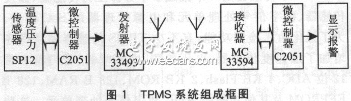
introduction Automobile tire pressure monitoring system (TPMS) is mainly used for real-time automatic monitoring of tire air pressure while the car is running, and alarming of tire leakage and low air pressure to ensure driving safety. As far as the structure of the TPMS system is concerned, the temperature and pressure data it collects need to be sent and received in a wireless manner, and the transceiver circuit must be installed in the tire. This must require the chips that make up the circuit to withstand high temperatures. To solve these two problems, you can use the transmitter chip MC33493 and the receiver chip MC33594 developed by Motorola. Both chips have reached automotive-grade temperature (125 ℃ for the transmitting chip and 105 ℃ for the receiving chip) can completely solve the problem of high temperature resistance, and the working performance is excellent. The interface circuit formed by them and the single chip has become an important part of wireless data transmission in the TPMS system. 1 Overall design of TPMS system 1.1 System working principle The TPMS system is mainly composed of a TPMS transmission module composed of a pressure and temperature sensor installed in a car tire, a signal processing unit, and an RF transmitter, an RF receiver including a digital signal processing unit and an LCD installed on the car's cab. In general, a car needs 4 TPMS transmitter modules and 1 TPMS receiver; and a truck needs 6 to 12 TPMS transmitter modules. In order to improve the receiving ability and anti-interference ability of the system, the receiving antenna should be installed on the chassis of the vehicle when the system is installed. The structural block diagram of the TPMS system program consisting of SP12 sensor, microcontroller, MC33493 transmitter module, MC33594 receiver module and other main chips is shown in Figure 1. In Figure 1, the temperature and pressure sensor sends the collected temperature and pressure data to the microcontroller through the I2C bus or RS232 interface, and the microcontroller sends an enable signal ENABLE to the transmitter. When it is at high level, the transmitter starts to work and generates a data clock signal to the single-chip microcomputer for signal synchronization. At this time, the MCU sends data to the transmitter, and the transmitter transmits the obtained data through the antenna. After the receiver receives the signal through the antenna, first set the RESET pin (used to set the master-slave mode) to a low level, then the microcontroller is the master, and the register in the receiver as the slave is set through the MOSI line After setting, set the RESET pin to high level. After that, the microcontroller becomes the slave, and the receiver becomes the master. It generates a clock signal and sends the received data to the microcontroller through the MOSI line. At this time, the single chip microcomputer (with SPI interface) realizes a simple connection with the PC through the SPI interface to achieve the function of displaying an alarm on the PC. 1.2 System design considerations ①Because the TPMS transmitter module works under conditions of severe vibration, large changes in ambient temperature difference and is not convenient for immediate maintenance, all devices are required to have good reliability and stability, and can be adapted to work in the temperature range of -40 ~ +125 ℃ . In order to reduce the size of the TPMS transmitter module, save power consumption and enhance functions, it is necessary to choose small RF transceiver chips with multiple functions as much as possible. ② With the increasing attention to energy issues, system energy saving has become a key issue for this design. In order to improve the working time of the TPMS transmitter module under a lithium battery, the system should be put to sleep for most of the time. To wake up the transmitter part of the TPMS system, you can use such a method: add an acceleration sensor to the sensor module, and use its sensitivity to movement to realize the automatic startup of the car when it starts and enter the system self-test; Intelligently determine the detection time period, and use software to set the safety period, sensitive period and dangerous period to gradually shorten the tour detection period and improve the early warning ability. To wake up the receiving part of the TPMS system, you can use a pin STROBE of the receiver. In a cycle, when a valid ID is detected, STROBE is set to a high level, at this time the receiving chip changes from the sleep state to the running state. 2 System hardware composition and circuit design 2. 1 TPMS system main hardware composition The TPMS system is mainly composed of TPMS sensors, microcontrollers and wireless RF transceiver modules. (1) TPMS sensor The TPMS sensor is an SoC module that integrates a semiconductor pressure sensor, temperature sensor, digital signal processing unit, and power manager. In order to strengthen the tire pressure detection function, many TPMS sensor modules also add acceleration sensors, voltage detection, internal clock, watchdog, and 12-bit ADC, 4KB Flash, 2KB ROM, 128 B RAM, 128 BEEPROM and other functions ASIC digital signal processing unit. These functional units make the TPMS sensor not only detect the changes in tire pressure and temperature within the tire in real time, but also realize the functions of instant start-up, automatic wake-up and power saving. (2) Microcontroller Here the microcontroller uses a small single-chip microcomputer 89C205l introduced by Atmel, which contains 2KB Flash program memory and 128 B of on-chip RAM. 89C2051 has 20 pins. Among them, the P1 port and 8 pins can be used as a general quasi-bidirectional port, which has a strong pull-down capability in the driving capability of the pin. The operating voltage is 2.7 to 6V. When the operating voltage is 3V, the current is equivalent to 1/4 of the 6V operation, 1mA when idle, and only 20mA when power is off. This small power consumption is very suitable for small battery-powered control systems. The main feature is the use of Flash memory technology, and its software and hardware are fully compatible with MCS-5l. The on-chip program's electrically erasable characteristics make it easier to develop and test. (3) Wireless radio frequency transmitting chip MC33493 Motorola's MC33493 device is a high-temperature integrated UHF radio transmission module. Two modulation methods are available: OOK (On-Off Keying) or FSK (Frequency Shift Keying). The chip is packaged in TSSOP-14 and works in the 300-450 MHz band; it has FSK and OOK modulation and demodulation capabilities, strong anti-interference ability, suitable for industrial control applications; using PLL frequency synthesis technology, good frequency stability; has a small Transmit power, the maximum transmit power reaches O.18mW; the data rate can reach 9.6kb / s; the low operating voltage of 1.9 ~ 3.6V; the power consumption is low, the current during launch is 11.6mA, and the launch standby state is only 0.8μA At 125 ° C). We specialize in waterproofing products overmolding. We can custom build, custom mold, and over-mold your cable designs.
We specialize in molded cable manufacturing for the widest diversity of
cable and connector types, across the whole spectrum of industries. Rich expeirence in developing and proposing solution Special for IP67, IP68 waterproofing products. Molded Waterproofing Cable Assemblies Molded waterproofing cable assemblies, waterproof wire harness, waterproofing cables overmolding ETOP WIREHARNESS LIMITED , https://www.etopwireharness.com