Research on Passive Intermodulation of Ship Communication System
introduction In a communication system, when two or more RF signals are transmitted through a device with nonlinear characteristics, an intermodulation product (IMP) will be generated in the synthesized signal. When these intermodulation products fall into the passband of a receiver working nearby, parasitic interference is formed. In the shipboard communication link, the active intermodulation interference generated by the transmitter and receiver can be minimized by appropriate system isolation, and PIM caused by passive nonlinearity cannot usually be suppressed by the same method. In theory, passive linear systems do not produce new frequency components. However, in fact, nonlinear changes are unavoidable in passive transmission systems, but when the carrier signal is small, passive intermodulation interference (Passive IntermodulaTIon Product, PIMP) caused by nonlinearity (passive intermodulation product (PIMP)) Passive IntermodulaTIon Interference (PIMI) is not big, and it is not noticed by people. But when the carrier signal is large, this intermodulation interference is more obvious. PIMP is usually produced in a multi-carrier communication environment. Typical examples are ship-based communication systems, ground mobile communication base stations and satellite ground receiving stations that share a broadband antenna feeder system. Especially, high-power transmission systems and high-sensitivity receiving systems are required to exist in both. The objective PIMI of a ship communication system with limited space cannot be ignored. 1 Introduction to Passive Intermodulation Historically, the PIM phenomenon was first observed on ships that require transceiver antennas to coexist in a limited space-this is what the industry calls the "Rusty bolt effect" ("rusty bolt effect"), which is due to the corrosion of antenna structural elements The phenomenon of communication interference [3j. Therefore, the earliest PIM research was conducted by the US Naval Research Laboratory (Naval Research Laboratory). In the mid-1970s, at the request of the military, an in-depth study of the PIMI problem caused by metal parts containing RF magnetic materials in RF connectors Later, it is recommended to prohibit the use of ferromagnetic materials in the revised version of the U.S. military specification MIL-C-390l2B "General Specification for Radio Frequency Connectors". It is strongly required that ferromagnetic materials be directly excluded, and the communication department must be reminded to be wary of any Potential problems, these suggestions are partially reflected in the future MIL-C-39012C version and Mll-PRF-39012 version. In these versions, the requirements for materials clearly stipulate that all parts (except air-tight connectors) should be made of non-magnetic materials, and the material permeability value should be less than 2.0. In addition, the material used for the center of the contact and the housing, the type of the plating metal and the thickness of the plating layer are specified. All of these are specific measures to prevent PlMI. These requirements are also partially reflected in China's military standard GJB681 and its revised version GJB681A. 1.1 The mechanism of passive intermodulation PIM is caused by the nonlinearity of passive devices. There are three possible main modes of passive nonlinearity, one is contact nonlinearity, the other is material nonlinearity, and the other is process nonlinearity. The former refers to any contact with nonlinear current and voltage behavior, such as unevenly bent coaxial cable, uneven waveguide flanges, loose tuning screws, loose riveting, oxidation and corrosion contacts, etc. Linear refers to materials with inherently nonlinear electrical characteristics, such as ferromagnetic materials and carbon fibers; the latter refers to the nonlinearity of electrical transmission caused by processing techniques. 1.1.1 Contact nonlinearity When two conductive connectors (such as plugs and sockets) are connected, according to the magnitude of contact force, force uniformity, contact surface flatness and metal oxidation degree, the following contact states will be formed: metal contact; there is sandwiched between contact surfaces Metal film oxide; insulating medium sandwiched between contact surfaces; tiny air gaps; large air gaps. Its non-linear contact surface and electronic model are shown in Figure 1. Due to the effect of surface roughness. Microscopically present irregular and uneven contact surfaces, mainly in the following contact states: The metal contact part â‘ and the metal film oxide contact part â‘¡ form the main channel of current, and the contraction resistance and film resistance formed can form the contact resistance of the conductor. The oxide in the metal-oxide-metal junction â‘¡ may be a single molecular structure, which is conductive by relying on the tunnel effect and the metal bridge penetrating the thin film, so it belongs to semiconductor contact conduction and is non-linear; sandwiched between the contact surfaces Contacts with insulating material â‘¢ are not conductive: current passes around the metal contacts. At large air gaps, current also flows around the gap. In both cases, the current encounters the impedance Z, generating a gap voltage, the gap voltage V is potentially, may activate any semiconductor and cause tunneling and microscopic arc breakdown. Components such as capacitance C, inductance L, and resistance R at the contact surface constitute an electronic circuit. Its equivalent circuit model is shown in Figure 1 (b), and its VI characteristics are nonlinear. At small gaps, due to current fluctuations or strong signals, it is easy to form microscopic breakdowns. These unstable breakdowns make the form of PIM accidental, and the amplitude changes with time. For the uncertain contact nonlinearity occurring near the zero-voltage region, it can be represented by Figure 1 (a). The quality of the contact state of the contact surface determines the degree of contact nonlinearity. The mechanism of contact nonlinearity to generate PIM mainly includes: (1) Mechanical effect caused by point mechanical contact; (2) Electronic effects caused by point electronic contact; (3) Thermal effect caused by point electronic contact and local large current; (4) Strong direct current causes ion migration in metal conductors; (5) Relative motion, vibration and wear of the contact surface; (6) Contact of devices with different coefficients of thermal expansion causes thermal cycling. In addition, there are loosening and sliding of metal contacts and the formation of oxide layers or contaminants. The aforementioned phenomenon of rusty bolts discovered by the US Naval Research Institute belongs to PIM caused by contact nonlinearity. 1.1.2 Material nonlinearity The mechanism of PIM caused by material nonlinearity is mainly manifested in: (1) Ferromagnetic effect. Ferromagnetic materials (iron, cobalt, nickel, etc.) have a large magnetic permeability, and exhibit a hysteresis characteristic with the nonlinear change of the magnetic field. Ferromagnetic materials can cause a strong PIMP, which is the main factor for PIM. (2) The tunnel runs through. The electrons are directly penetrated by a tunnel from one conductor to another through a thin dielectric layer with a thickness of less than 10 nm, such as the electron tunneling effect between metals separated by an oxide layer. (3) Contact capacitance. Capacitance caused by contact with thin layers and contaminated layers. (4) Electrostriction. The electric field can cause linear changes. The electrostriction in pure non-polar dielectrics is one of the factors that cause PIM in coaxial cables. (5) Magnetostriction. The magnetic field can also cause linear changes, which are mainly generated in ferromagnetic materials. (6) Micro discharge. There may be micro slits and trachoma in the material, and the secondary electron multiply discharge caused by the generation of ionic gas under a strong electric field in a vacuum environment. (7) Space charging. Charged carriers enter the insulator or semiconductor at the contact point. This effect is generated in a non-uniform internal electric field. In the semiconductor application, due to the simultaneous presence of electrons and holes, it can generate a strong nonlinear current-voltage relationship. In addition, there are material nonlinearities caused by ion conduction, thermal breakdown and dielectric breakdown caused by avalanches, and thermal ion emission effects. 1.1.3 Non-linear process The general RF connectors will be surface planed and electroplated. The processing technology determines the surface flatness and the thickness of the plating layer. An overly rough surface and an inappropriate coating thickness will cause passive nonlinearity, which in turn leads to passive intermodulation-this can be explained by the "skin effect", that is, "DC current flows uniformly along the entire cross-section in the conductor The same density flows, and the RF current tends to the "skin" on the surface of the conductor. As the frequency increases, this "skin" becomes thinner. This kind of electricity The phenomenon that the current flows to the surface of the conductor is called the "skin effect". Although it is difficult to fully explain the mechanism of non-linearity due to the quality of electroplating, production practice has proved that the quality of electroplating does affect the level of PIM production. The skin depth determines the thickness of the plating layer. The assembly process of RF cables / waveguides and connectors also affects the PIM index, which has a similar mechanism to contact nonlinearity. 1.2 Features of passive intermodulation It is known that active intermodulation refers to two or more interfering signals generated by the nonlinearity of the active circuit at the front end of the receiver. As long as the frequency of the intermodulation signal is equal to or close to the useful signal frequency, active intermodulation interference will occur: (1) The nonlinearity of the active circuit is relatively fixed and does not change with time. (2) Predictable by the nonlinear characteristics, the analysis theory is relatively mature. (3) The indicators are clear. Military standards or specifications can give clear indicator requirements. (4) The transmission direction is relatively stable. It can be suppressed by adding bandpass / bandstop filters or improving filter performance, and high-order intermodulation interference is almost ignored. Compared with active intermodulation, passive intermodulation presents the following characteristics: (1) Varies with power. The US Naval Research Institute studied the relationship between PIM generation levels and input power. Generally speaking, the greater the input power, the greater the PIM. The American Amphenol experiment confirmed that for every dBm input power change, the PIM level changes by about 3 dBm. The industry generally believes that the ratio of 1: 3 is basically reasonable. (2) Changes with time. The surface oxidation of the material, the contact pressure at the connection, and the degree of bending of the cable will change with time, which will affect the degree of nonlinearity. The examples later in this article also confirm this. (3) Research theory lags behind. The accurate prediction of passive nonlinear characteristics is difficult. So far, some phenomena have not been fully confirmed by theory. There is no substantial breakthrough in simulation research methods, and there is still a considerable distance from engineering. (4) There are many links and the transmission direction is not single, so it is difficult to suppress it by traditional means. (5) High-order intermodulation exists and is still worrying. 1.3 The expression of passive intermodulation When a Vi (t) signal with frequency f1 and amplitude A1 is passed through a passive two-port component with nonlinear VI characteristics, its output signal Vo (t) contains multiple harmonics in addition to the fundamental wave: It can be seen from Figure 2 that the odd-order intermodulation component is adjacent to the fundamental frequency and the amplitude of the component is large, which may enter the passband of human reception, thereby forming interference. For high-order intermodulation and even harmonics, the receiver RF filter can usually be filtered out because it deviates far from the fundamental frequency, so passive third-order intermodulation (PIM3) is the focus of attention, and should usually be included in the technical indicators Be clear. PIMP is usually expressed in dBm or dBc. dBm is the power in decibels per day with zero power level (0 dBm) as the reference quantity P0 = 1mW. dBc is a decibel measurement at a specified carrier level (such as 20W, or 43dBm). The power level of any power Px is defined as:
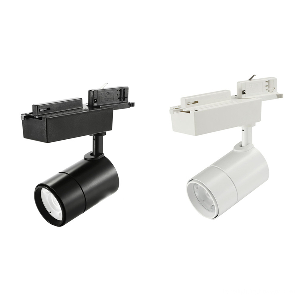
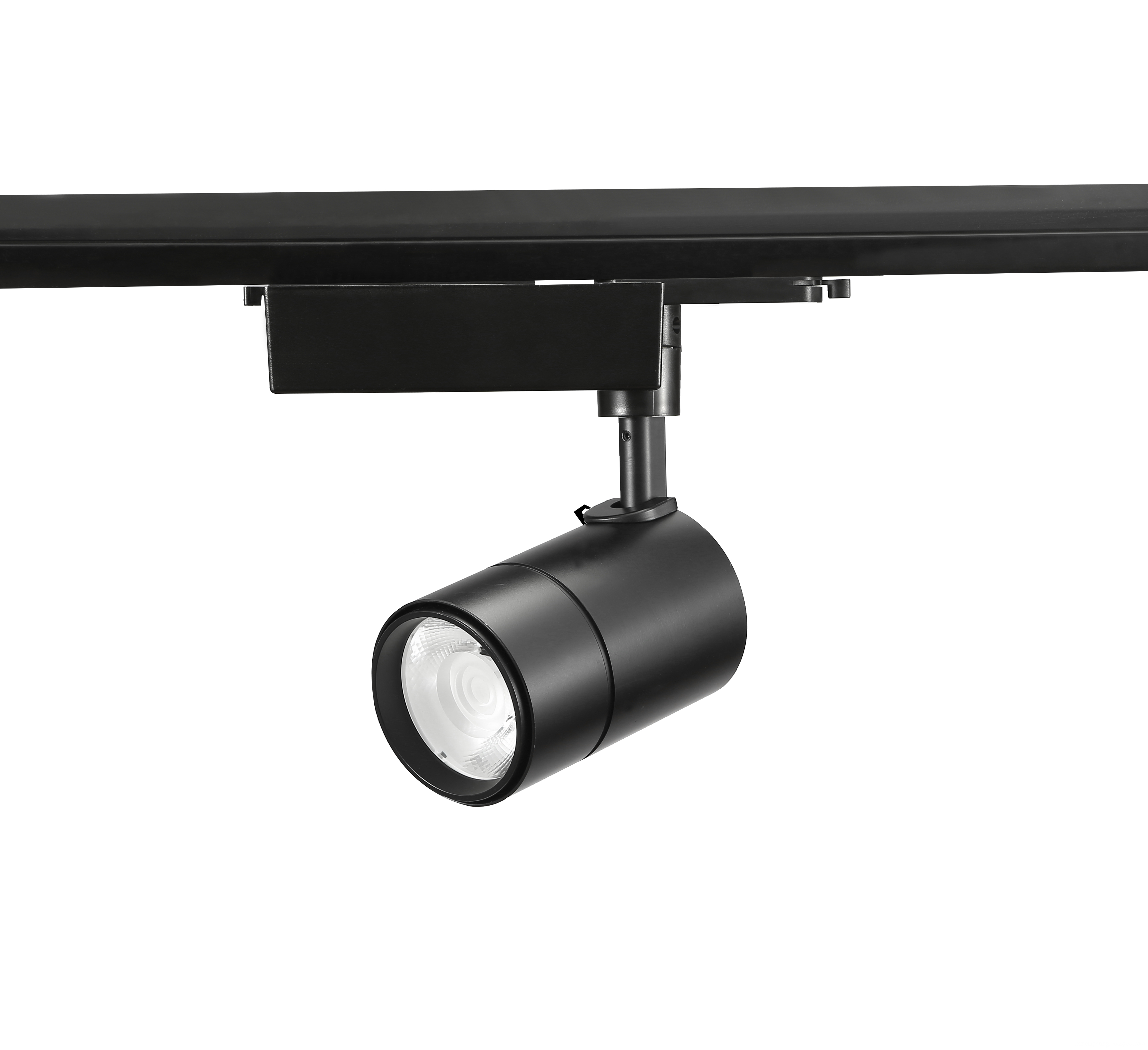
25W LED Track Lights,
25W LED Track Lights 25W Dimmable LED Track Light, 25W Mini LED Track Lighting, 25W Commercial LED Track Light, 25W Color Changing LED Track Light SHENZHEN KEHEI LIGHTING TECHNOLOGY CO.LTD , https://www.keheiled.com
Figure 1 Contact nonlinear surface and its electronic circuit model 
When more than two signals pass through a non-linear network, the output signal Vo (t) contains not only the fundamental wave and each harmonic, but also various components of the generated PIMP. It is quite complicated to express it by the transmission equation. Here, the PIMP frequency component fPIM is expressed as: 
Where: m and n are integers, (| m | + | n |) is defined as the order of the intermodulation product. This formula can be used to describe any communication system with a multi-channel radio frequency input signal sharing non-linear transmission device to determine the possible PIMP. The spectrum distribution is shown in Figure 2. 
Figure 2 Schematic diagram of the frequency spectrum after two signals pass through a nonlinear network 
If the level of PIM3 measured at Pf1 = Pf2 = 20 W is -100 dBm, then expressed in dBc as: 
Light Source: COB Bridgelux or Luminus.
25W LED Track Lights with international single phase, 2 phase, 3 phase track connector.
CCT: warm white, pure white, cool white are available.
Function: Non-dimmable, dimmable and CCT changeable are available.
Types: DALI system, 0-10V systerm, Dial Switch, guide rail with power supply are available.
Beam Angle: High reflectance diffuser (Lens+Reflector) with 12° / 24°/ 36° for choice.
Dimension of 25W Led Track Lights: Φ80mm, 63*211*190mm
Finished Color: Matt White / Black / Silver etc.
High luminance flux: 1960lm
High CRI: >90Ra
Input voltage: AC110/220V 50/60Hz
Certification: CE RoHS


