The secret of robot autonomous movement, starting from SLAM technology
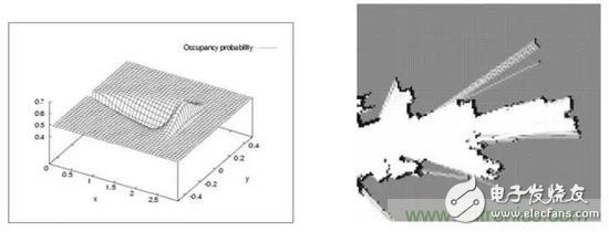
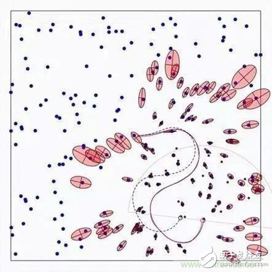
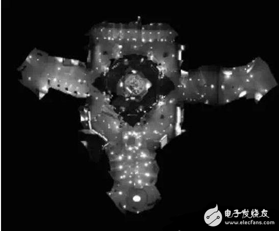
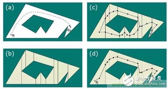
Intelligent service robots are becoming the cusp of the industry. Starting from cleaning robots, family companion robots and food delivery robots have entered the public eye. When discussing whether such robots can solve practical problems, autonomous positioning navigation technology as the first step of robot intelligence is constantly attracting attention in the industry. At the same time, as an important breakthrough in autonomous positioning navigation technology, SLAM technology has also become the focus of attention. As shown in the figure, the robot autonomous positioning navigation technology includes positioning, map creation and path planning (motion control), while SLAM itself only completes the positioning of the robot and map creation, which are different. So, how is SLAM technology implemented? What are the difficulties? How does the robot implement path planning and automatic navigation? What kind of sweeping robot is smart? These questions, Xiaobian will answer you one by one, leading everyone to understand the secret of robotic autonomous movement. SLAM is an abbreviation for Simultaneous LocalizaTIon And Mapping, first proposed by Hugh Durrant-Whyte and John J. Leonard. In fact, SLAM is more like a concept than an algorithm. It itself contains many steps, each of which can be implemented using different algorithms. It is mainly used to solve the problem of real-time positioning and map construction when mobile robots are running in an unknown environment. When you are in a different place, how can you find exactly where you want to go? How do you find a way home when you get lost outdoors? Yes, we have navigation software and outdoor maps. Like human mapping, the process of robots describing the environment and understanding the environment is mainly relying on maps. It uses an environmental map to describe its current environmental information and uses different map descriptions as the algorithm and sensor used. There are four ways to represent maps in robotics: raster maps, feature maps, direct representations, and topological maps. 1, raster map The most common way for a robot to describe an environment map is a Gridmap or OccupancyMap. A raster map divides the environment into a series of rasters, each of which gives a possible value, indicating the probability that the raster is occupied. This map looks no different from the maps that people recognize. It was first proposed by NASA's AlbertoElfes in 1989 and used on Mars rover. The essence is a bitmap image, but each of them is " "Pixels" means the probability distribution of obstacles in the actual environment. In general, the map can be used when a sensor that can directly measure distance data such as a laser radar, a depth camera, an ultrasonic sensor, or the like is used for SLAM. This map can also be drawn by distance measuring sensors, ultrasound (early), and lidar (now). 2. Feature point map The feature point map is an environment that uses related geometric features (such as points, lines, and faces), and is commonly found in vSLAM (Visual SLAM) technology. This map doesn't look so intuitive compared to raster maps. It is generally generated by the vSLAM algorithm such as GPS, UWB and camera with sparse mode. The advantage is that the relative data storage amount and computation amount are relatively small, which is more common in the earliest SLAM algorithm. 3. Direct characterization In the direct characterization method, the intermediate link of feature or grid representation is omitted, and the data read by the sensor is directly used to construct the pose space of the robot. The picture above is an image map that directly records the ceiling image of the house. This method, like a satellite map, directly integrates sensor raw data into a map by simple processing, which is relatively more intuitive. 4, topology map Topological map, a relatively more abstract form of map, represents the indoor environment as a topological map with nodes and associated links, where nodes represent important locations in the environment (corners, doors, elevators, stairs, etc.) ), the side indicates the connection relationship between the nodes, such as the corridor. This method only records the topological link relationship of the environment. Such maps are generally extracted from the previous types of maps through correlation algorithms. For example, when the sweeping robot is going to clean the room, it will create such a topology map: 5. Summary In robotics, SLAM's map construction usually refers to the creation of maps that are consistent with the geometry of the environment. The topology map established in the general algorithm only reflects the connection relationship of each point in the environment, and can not construct a geometrically consistent map. Therefore, these topological algorithms cannot be used for SLAM.
Product Features
1, built-in over-current overheating, temperature control circuit technology.
2, the module design, easy installation, online replacement.
3, low leakage current, fast response time, low residual voltage.
4, alarm indication device, green (normal) v red (fault).
Maximum Discharge
Current Imax(8/μ20μs)kA
Nominal Discharge
Current In(8/μ20μs)kA
Operating
Environment-C
Surge Protector SPD,Surge Protection Device SPD,SPD Wenzhou Korlen Electric Appliances Co., Ltd. , https://www.zjthermalrelay.com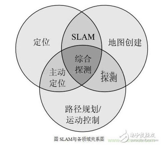
Product Description
SPD Surge Protective Device,Lightning Surge Protector
Surge Protection Device (SPD)
It is a device used to limiting instant surge voltage and discharge surge current, it at least including a non-linear component.
Surge protective Device Model Selection
With the impact of international information flow, the rapid development of microelectronic science and technology, communication, computer and automatic control technology, make the building start to go for high quality, high functional area, formed a new building style-intelligent building. As inside the intelligent building there are lot of information system, <<Building lightning protection design norm>> GB50057-94(2002 vision)(hereafter brief as <<lightning protection norm>>) put forward the relative requirement to install the surge protective device, to ensure the information system safely and stable running.
SPD essentially is a equipotential connection material, its model selection is according to the different lightning protection area, different lightning electromagnetic pulse critical and different equipotential connection position, decide which kind of SPD used in the area, to achieve the equipotential connection with the common earth electrode. Our statement will based on SPD's maximum discharge current Imax, continuous operating voltage Uc, protection voltage Up, alarm mode etc.
As per << Lightning Protection Norm>> item 6.4.4 stipulation "SPD must can withstand the expected lightning current flow and should confirm to the additional two requirements: the maximum clamp voltage during surge across, capable to extinguish the power frequency follow-on current after lightning current across." That is the value of SPD's max. clamp voltage add its induction voltage of two ends should be same with the system's basic insulation level and the equipment allowed max. surge voltage.
SPD for Power Supply System Series Selection Guide
The installation of SPD at each lightning protection zone, according to the standard of low voltage electrical appearance, make classification of electrical equipment in accordance with the over voltage category, its insulation withstand impulse voltage level can determine the selection of SPD. According to the standard of low voltage electrical appearance, make classification of electrical equipment in accordance with the over voltage category as signal level, loading level, distribution and control level, power supply level. Its insulation withstand impulse voltage level are:1500V,2500V,4000V,6000V. As per to the protected equipment installation position different and the different lightning current of different lightning protection zone, to determine the installation position of SPD for power supply and the break-over capacity.
The installation distance between each level SPD should not more than 10m, the distance between SPD and protected equipment should as short as possible, not more than 10m. If due to limitation of installation position, can't guarantee the installation distance, then need to install decoupling component between each level SPD, make the after class SPD can be protected by the prior class SPD. In the low voltage power supply system, connecting an inductor can achieve the decoupling purpose.
SPD for power supply system specification selection principle
Max. continuous operating voltage: bigger than protected equipment, the system's max. continuous operating voltage.
TT System: Uc≥1.55Uo (Uo is low voltage system to null line voltage)
TN System: Uc≥1.15Uo
IT System: Uc≥1.15Uo(Uo is low voltage system to line voltage)
Voltage Protection Level: less than the insulation withstand impulse voltage of protected equipment
Rated discharge current: determined as per to the lightning situation of the position installed and lightning protection zone.
SP1 Series
Normal Working Conditions
-Altitude not exceed 2000m
-Ambient air temperature:
Normal range: -5ºC~+40ºC
Extend range: -40ºC~+80ºC
-Relative Humidity: 30% - 90% under indoor temperature condition
- At the place without obviously shaking and shock vibration
- Non-explosion danger medium, non-corrosion gas and dust ( including conductive dust)
Classification
-As per Nominal Discharge Current:
5,10,20,30,40,60KA(8/20µs)
- As per Maximum continuous operating voltage:
275V,320V,385V,420V,440V,460V
- As per to poles
1P,1P+N,2P,3P,3P+N,4P
- As per auxiliary functions:
a. With remote signal output ( remote alarm function)
b. Without remote signal output
Selection Principle
- The continuous applied voltage on the two terminals of SPD should not more than the maximum continuous operating voltage Uc value;
- The voltage protection level Up of SPD should less than the maximum impulse withstand voltage of the protected equipment;
- As per to the different earthing system and protection mode to select the specification accordingly;
Model/Technical Parameters
WR-B60
WR-B80
WR-B100
WR-B120
WR-B150
Rated Operating Voltage Un (V ~)
220V 380V
220V 380V
220V 380V
220V 380V
220V 380V
Maximum Continuous Operating Voltage Uc (V ~) kV
385V 420V
385V 420V
385V 420V
385V 420V
385V 420V
Voltage Protection Level Up (V ~) kV
≤1.8≤2.2
≤2.4≤2.5
≤2.5≤3.2
≤3.4≤3.7
≤4.0≤4.5
60
80
100
120
150
30
40
60
80
100
Response Time
<25
<100
L/N(mm²)The Cross Section Of L/N Line
16,25
16,25
16,25
16,25
25,35
PE (mm²)The Cross Section Of PE Line
16,25
25,35
25,35
25,35
35
Fuse or Switch (A)
63A
63A
63A,100A
63A,100A
63A,125A
The Line Section of Communication and Alarm (mm²)
≥ 1.5
(-40ºC~-+85ºC)
Relative humidity 25 ºC
≤95%
installation
Standard Rail35mm
Material of Outer Covering
Fiber Glass Reinforced Plastic