Realization of intelligent iontophoresis based on MCU intelligent injection device
Iontophoresis (Iontophoresis) is a treatment that penetrates the drug into the body through the skin. Drugs that are absorbed through the skin are a type of charged mixture that is driven through the skin by an electric current. To inject a proper dose of drugs, it is necessary to effectively control the current through the skin. This operation can be achieved by using an automated system. Most of 3528 RGB LED are widely used in LED shoe light, LED strip light, LED display, LED light bar, LED electronic light board ect. 3528 RGB LED 3528 RGB LED, 3528 RGB LED Strips, Highlight 3528 RGB LED, Waterproof 3528 RGB LED, SMD 3528 RGB LED Shenzhen Best LED Opto-electronic Co.,Ltd , https://www.bestsmd.com
There are many benefits of iontophoresis. First of all, it is possible to administer a very high dose locally (in humans) instead of the whole low dose. Secondly, the side effects of topical medicine are much less. Through high-dose medication, the efficacy of the drug can be greatly improved. To do this, prepare specially formulated medicines, which are combined with electrons and transmitted by the current flowing through the skin. In the past, this required a large number of electronic components and a trained nurse to monitor the current, and the drip device needed to have the necessary safety features to protect the patient. However, with the advancement of technology in recent years, the design of switch-mode power supplies and the emergence of cost-effective, high-performance microcontrollers (MCUs), low-cost or disposable infusion sets have become possible. This article describes how to use a low-cost 8-bit PIC12F683 microcontroller with mixed-signal function and some off-the-shelf components to achieve this conceptual design. 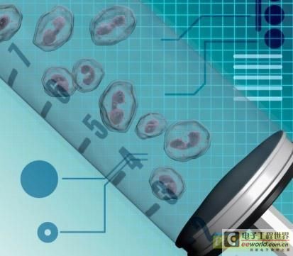
achieve
To inject drugs through the skin, the injection device must generate enough voltage to drive the current in order to provide a specific drug injection rate within the required administration period. The purpose of (design) is to control the current through the skin, but for safety reasons, it should be ensured that the device does not generate excessive voltage. Otherwise, the injection device may break away from the patient and break down the current channel. In this case, the control circuit will try to increase the voltage to maintain the current flow rate, and reconnecting the (injection device) may make the patient feel uncomfortable.
A boost regulator is used to gradually increase the voltage from the low-voltage battery to a sufficient level to allow the required current to flow through the skin. The intermittent boost regulator topology is chosen because it does not require the processor to provide pulses at specific times, allowing the current through the inductor to drop to zero. This can simplify software development.
The MCU is configured with an external asynchronous reset pin (master reset / MCLR). Lowering the level of this pin will reset and wake up the microcontroller in a low-power shutdown state (sleep). Once a certain infusion is completed, the software immediately goes to sleep. The button connected to the MCLR pin sets the line low and wakes it from sleep mode. When the device wakes up from sleep, it starts to execute the code from the reset vector (0x0000 in the program memory), and other reset (including power-on) codes are also the same. The amount of infusion to be managed is stored in the internal EEPROM, which mainly depends on the implementation and the medicine being managed. This circuit uses two AA alkaline batteries to power the microcontroller and the switching regulator.
The software uses the microcontroller's built-in analog-to-digital converter (ADC) to monitor the voltage applied to the skin and compare it with a set threshold. If the voltage applied to the skin exceeds a predetermined value, the MCU will stop switching the MOSFET to avoid raising the voltage too high. This function limits the output voltage to a safe level, so that the device will not fall off from the skin of the person being injected. The predefined limit is set by the software, but because the voltage applied to the skin may be greater than the voltage that the MCU input pin can withstand or greater than the voltage that its ADC can convert, it is necessary to convert this value in proportion. The applied voltage is converted from the resistors R1 and R2 shown in Fig. 2 to the range of the power rail of the microcontroller--0 ~ 3V.
Generally, the amount of current used in iontophoresis varies with the drug, and needs to be confirmed according to the specific prescription. The current is controlled by an external resistor R3 of the PIC12F683 and an internal comparator. By defining the desired current, the range is 0.5 ~ 4 mA, and the threshold of the comparator is set in the code.
The software determines the current value by testing the output of the comparator. If the current exceeds the expected value, then the microcontroller will not switch the MOSFET. Otherwise, the MOSFET is converted to boost, driving more current through the skin. The output current is equal to the power of the input pin multiplied by the efficiency of the converter, and then divided by the output voltage, as shown in the following formula: 
The duration of infusion is controlled by a built-in 16-bit hardware timer and a 16-bit software timer. When the expected dose is reached, the microcontroller stops switching the MOSFET and goes to sleep, and then waits for the next button to start. To increase patient comfort, the output voltage rise rate during the power-up sequence can be adjusted. 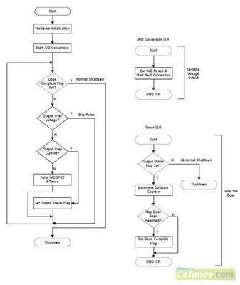
2. The simplicity of the design can be seen from the circuit schematic
In the circuit schematic (Figure 2), Q1 is the main switching transistor. The breakdown voltage of MOSFET Vds and D1 should be greater than the maximum expected output voltage of the circuit. When the microcontroller detects that the output current is lower than expected, it will pulse the MOSFET four times in quick succession to increase the voltage output. These four pulses will produce more current and rise time under accelerated load. Alternatively, PWM can be used to drive the MOSFET, which allows higher output from the boost circuit. R6 / C6 is the current detection network.
Because PIC12F683 is small in size, low in cost, and equipped with internal ADC, fixed reference voltage, integrated comparator, PWM, hardware timer and internal EEPROM, it was selected as MCU by this design. Using a fixed reference voltage eliminates the need for regulators or external reference voltages, making the design an 8-pin device to further reduce costs.
The design also contains two LEDs for the user interface and a start button connected to the reset component.
Test Results
During the test, the waveforms shown in Figures 3 and 4 were captured. 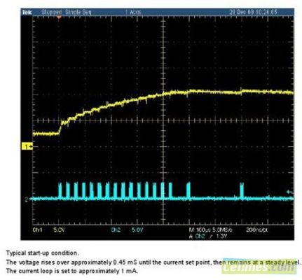
A start waveform when using a 10K load. 
Use a starting waveform at 20k load.
Using a 1μF ceramic capacitor as the output capacitor, the voltage ripple is shown in Figure 5. 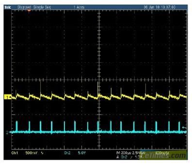
Adjust the output waveform when using a 20K load.
Usually we package the chip with 3.5*2.8mm plastic(ceramic) cup, it inclued black cup and white cup.
White cup RGB LED is brighter than the black cup RGB LED. The former is widely used in LED shoe light, LED strip light, LED light bar, LED electronic light board ect.
The latter is used in LED display.