Circuit design scheme of automobile taillight and central brake light
Light-emitting diodes (LEDs), which have long been used in consumer electronics, have also recently been used in the field of automotive lighting to provide signal functions, daytime running lights and interior lighting. With the increasing popularity of this lighting technology, manufacturers are constantly researching new application methods in order to give full play to the advantages of LED headlights and taillights.
For Led Lighting System,Specifically for led downlight,outside Constant Current Led Driver, Plastic casing, AC100-277V input, 27-40/42V output,with the dimming function of triac-dimming/0-10V/PWM/RX. Flicker free and SELV Safety output design, UL/FCC/TUV/RCM/CB/CE Certified.
Parameter:
Input voltage:100-130V/100-277V/100-240V/180-240V
Output voltage:25-40V/27-42V
Current:250mA, 300mA, 350mA
Power factor: >0.9
Led Downlights Driver,350Ma Led Driver,Led Lighting System ShenZhen Fahold Electronic Limited , https://www.fahold.com
Red LEDs are now widely used in tail lights. Although cost is still an issue, safety, environmental protection and flexible styles and other factors tend to adopt LEDs. One of the most popular applications is the central brake light. This design concept shows the method of using the same LED array for the taillights and brake lights. 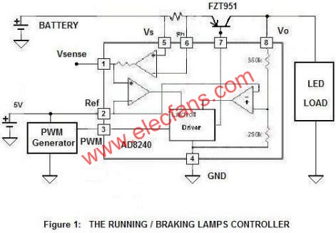
Figure 1: Driving / brake light controller
The brightness of the LED is controlled by a simple switch, which dims when driving and brightens when braking. The functional block diagram is shown in Figure 1, including the Led Driver / monitor AD8240, PNP regulator and PWM generator. The AD8240 provides a constant voltage to drive the LED lamp. It also provides cost-effective LED lamp monitoring and short circuit protection. When the battery voltage is between 12.5 V and 27 V, the output is stable at 12 V.
Figure 2 shows the PWM generator, which consists of two 555 timers. The PWM signal controls the LED brightness. When the PWM input is high, VO turns on; when the PWM input is low, VO turns off. The AD8240 is designed to operate at frequencies up to 500 Hz, with a typical duty cycle ranging from 5% to 95%. 
Figure 2: PWM signal generator
AD8240 provides a low-power, low-cost, small package solution. The internal current-sense amplifier measures the voltage across the external shunt resistor; when the current measurement falls below the preset threshold, it indicates that an open LED has occurred. When the current reaches the level set by the external shunt resistance value, the output voltage will be locked, thereby limiting the output current. When the output of the sense amplifier exceeds 5 V, the internal comparator will cause the driver to lock the output voltage. In the next PWM cycle, the latch is reset. By measuring the output of the sense amplifier, the overcurrent condition can also be detected.
Since the inductor required for the switch design is not needed, the cost can be further reduced; and the operating power consumption of the LED lamp is much lower than that of the incandescent lamp, so no switch driver is required.
The switching of the LED depends on the digital voltage on the CMOS-compatible PWM pin (AD8240 pin 3). For simple switch control, this voltage can be continuous; for dimming control, this voltage is PWM. The PWM frequency should be below 500 Hz, and the duty cycle should range from 5% to 100%. Typical values ​​are 5% (when driving) and 95% (when braking). In Figure 2, the PWM frequency is determined by R1, R2, and C1 of timer A1. The pulse period is:
T = 0.693 (R1 + 2 R2) C1
When R1 = 49.9 kΩ, R2 = 10 kΩ, and C1 = 0.1 μF, the period is 4.84 ms, or approximately 206 Hz.
Timer A2 converts this signal to a pulse width modulated signal, the duty cycle of which is determined by R3, R4, R5, and C2. The pulse width is determined by the following formula:
Pulse width = 1.1 RC2
Where R is equal to the parallel resistance of R5, R3 and R5 or the parallel resistance of R4 and R5, depending on the switch position. When R3 = 2.37 kΩ, R4 = 45.7 kΩ, R5 = 42.4 kΩ, C2 = 0.1 μF, the duty cycle is 5% (switch in position 1), 50% (switch in position 2) or 95% (switch in OFF position).
Please note that the LED brightness increases as the duty cycle increases. When the brake is depressed, the duty ratio is 95%, and the LED array is the brightest. During normal driving, the duty cycle is 5% and the LED array is dimmed. Two working states share a LED array can reduce costs.
If a short circuit or overload condition occurs, the voltage on Vsense (Pin 1) drops to 0 V and the output is turned off. This circuit will reset in the next PWM cycle. If this continues, the AD8240 will try to drive the output to 12 V, shut down and restart after each PWM cycle.
This circuit provides a method of driving and monitoring LEDs with only two wires (power and ground) using a constant voltage. Many designs use a chassis or shared ground return, in which case two wires can be reduced to one wire. Currently, these lights are controlled and driven by the body control ECU (Electronic Control Unit). With this constant voltage architecture, the control and drive functions of the LED remain in the ECU, and only minimal design modifications are required.
Dimming:0-10V / PWM / RX / Traic
>=50000hours, 3-5 years warranty.

FAQ:
Question 1:Are you a factory or a trading company?
Answer: We are a factory.
Question 2: Payment term?
Answer: 30% TT deposit + 70% TT before shipment,50% TT deposit + 50% LC balance, Flexible payment
can be negotiated.
Question 3: What's the main business of Fahold?
Answer: Fahold focused on LED controllers and dimmers from 2010. We have 28 engineers who dedicated themselves to researching and developing LED controlling and dimming system.
Question 4: What Fahold will do if we have problems after receiving your products?
Answer: Our products have been strictly inspected before shipping. Once you receive the products you are not satisfied, please feel free to contact us in time, we will do our best to solve any of your problems with our good after-sale service.