LED driver for car taillight
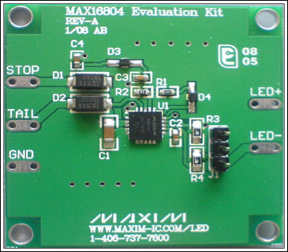
Abstract: The taillights and brake lights of most cars use the same set of LEDs, which requires the LEDs to work in two different brightness levels: when they are braked, they are fully bright, and when they are used as taillights, they are at 10% to 25% full brightness Dimming). The dimming method is best to choose pulse width adjustment (PWM), which can maintain the LED color spectrum in the entire brightness range. In addition, the use of an LED driver IC with a built-in 200 Hz oscillation circuit can eliminate the external PWM signal generator and simplify the design. This application note uses the MAX16804 high-brightness LED (HB LED) driver. The MAX16804 has a dual-mode DIM pin and a built-in 200Hz oscillation circuit, which eliminates the need for an external PWM signal generator and simplifies driver design. The tail light (adjustable LED brightness) and brake light (full light state) are controlled by the TAIL and STOP input of the LED driver. When a voltage is applied to the TAIL terminal, the tail light LED is driven to 10% to 25% of full brightness. When a voltage (brake) is applied to the STOP terminal, the LED is driven to the full brightness state (regardless of the state of the TAIL terminal input). Taillight driver specifications The input power supply voltage (between STOP or TAIL and ground) is nominally 6V to 16V, and may reach 45V under load dump. The output voltage (VLED) can be up to (VIN-1.4V). The output current (LED current) when braking is 350mA, 240mA or 140mA, depending on the J1 setting. The duty cycle of the PWM signal of the LED current of the taillight is 20%. Input STOP: An input voltage of 6V to 16V is applied between STOP (+) and GND (-) to drive the LED with a continuous current of 350mA, 240mA or 140mA, and the current size is set by J1. TAIL: An input voltage of 6V to 16V is applied between TAIL (+) and GND (-), and the LED is driven at 350mA, 240mA or 140mA with a 10% duty cycle, and the current is set by J1. Output LED +: Connect LED anode. LED-: Connect to the LED cathode. Circuit description LED drivers for automotive taillights (STOP and TAIL modes) can be easily implemented using linear LED driver ICs (eg MAX16804), requiring very few external components. Please refer to the driver circuit schematic diagram (Figure 1) and PCB layout (Figure 2). The maximum current flowing through the LED is set by R3 or R4, controlled by the connection mode of J1, the brightness is controlled by the PWM signal, and this function is realized inside the IC. The driver IC generates a 200Hz LED current adjustment signal, and the duty cycle depends on the voltage at the DIM terminal. For example, when the voltage at the DIM terminal is 0.78V, the tail light brightness is set at 20% of full brightness. Figure 1. MAX16804 high-brightness LED driver evaluation board circuit schematic The STOP and TAIL inputs are connected to the IN pin through diodes D1 and D2. The IC can be powered by any input terminal, and the inputs will not affect each other. D1 and D2 can also provide reverse voltage protection in the event of spikes in the automotive power bus. Capacitors C4 and C3 can bypass any noise on the STOP power line and provide protection for the DIM pin. Figure 2. The MAX16804 evaluation board PCB (the schematic is shown in Figure 1) Taillight running lighting working mode A fixed 0.78V voltage is generated from the TAIL input to the DIM terminal (generated from the + 5V regulated output), and the driver converts this voltage to a 20% PWM duty cycle to adjust the LED current. The PWM duty cycle in TAIL mode is independent of the input voltage at the TAIL terminal, and the DIM voltage in TAIL mode is set by the resistor divider R1 / R2. If the duty cycle setting is not equal to 20%, the corresponding DIM voltage (VDIM) can be calculated according to the following formula: Among them, D is the required duty ratio. Select R1 and R2 according to Equation 2 to meet the DIM voltage requirements: Among them, 0.6V is the forward voltage of diode D2, 5V is the output of the regulator, and VDIM is the required DIM pin voltage to meet the requirements of the PWM duty cycle. In order to avoid the influence of the input bias current on the DIM terminal to affect the DIM voltage, R2 is selected to be around 20kΩ. Brake mode In order to obtain a 100% duty cycle, the DIM voltage needs to be set above 3.1V. When the input voltage is applied to the STOP terminal, the DIM terminal obtains sufficient driving voltage through D3 to ensure a 100% PWM duty cycle. At this time, no matter what voltage is input to the TAIL terminal, the LED will be driven with a continuous current of 350 mA. LED current setting The MAX16804 EV kit circuit can set three different currents (140mA, 240mA, or 350mA) via jumper J1: J2 jumper connecTIon1 and 22 and 3Open LED current350mA240mA140mA If different current settings are needed, the current-sense resistance (R3 or R4) can be calculated according to the following formula. Among them, 0.198V is the current detection voltage, IOUT is the required LED current, the unit is ampere. Power consumption The device (MAX16804) can dissipate 2.758W of power. In this application, the power consumption is the largest in STOP mode, and the maximum power consumption is calculated according to the following formula. Among them, VIN is the input voltage of the IN pin, VLED is the forward voltage of the LED string, 350mA is the maximum LED current set through the jumper J1. Most of the device power dissipation is dissipated through the exposed pad. To improve heat dissipation, the exposed pad should be soldered to the board pad of the same area, and multiple vias are used to connect the exposed pad to the copper area of ​​the ground . Note: The MAX16804 EV kit can dissipate the maximum rated power at a room temperature of 25 ° C. When the ambient temperature is high, the power dissipated will be reduced. To prevent the IC from entering the thermal shutdown state, the power consumption should be properly reduced at high temperatures. You can download (PDF) to get the list of components used in the circuit board and the PCB layout. Power-up sequence LED + is connected to the anode of the LED or LED string, and LED- is connected to the cathode of the LED or LED string. In order to obtain 350mA of LED current, select pins 1 and 2 connected to J1. In STOP mode, the power supply voltage is connected between STOP (+) and GND (-), the minimum voltage is 6V, which is at least 1.4V higher than the LED forward voltage. In TAIL mode, remove the STOP power supply and connect the power supply voltage between TAIL (+) and GND (-). Test Results Figures 3–6 show the LED current test waveforms in STOP and TAIL mode. The maximum LED current is set at 350mA and 240mA. In STOP mode, the LED is in full brightness state (Figure 4 and Figure 6). After the supply voltage is applied between the STOP input and ground, the LED current will quickly rise to the set value (350mA or 240mA) to drive the LED with continuous current. There is no overshoot. Figure 3. In TAIL mode, the 350mA LED current is set by a 1Ω current-sense resistor, with a 12V VIN and 9.3V LED forward voltage. Using the PWM signal of 200Hz and 20% duty cycle to adjust, the LED brightness in TAIL mode is 20% of the maximum value, and the LED current amplitude is 350mA. In TAIL mode (Figure 3 and Figure 5), the 200Hz, 20% duty cycle PWM control signal only allows current to flow through the LED within 1/5 cycle, thus reducing the LED brightness. In STOP and TAIL modes, the LED current amplitude is precisely adjusted to the set value, and the restricted rise and fall times help to improve the EMI index. Figure 4. In STOP mode, the 350mA LED current is set by a 1Ω current-sense resistor, and the 12V VIN and 9.3V LED forward voltage. In the STOP mode, the LED is required to be in a full brightness state, and the LED is driven with a continuous current of 350 mA. Figure 5. In TAIL mode, the 240mA LED current is set by a 1Ω current-sense resistor, and the 12V VIN and 9.3V LED forward voltage. Using the PWM signal of 200Hz and 20% duty cycle to adjust, the LED brightness in TAIL mode is 20% of the maximum value, and the LED current amplitude is 240mA. Figure 6. In STOP mode, the 240mA LED current is set by a 1Ω current-sense resistor, and the 12V VIN and 9.3V LED forward voltage. In the STOP mode, the LED is required to be in a full brightness state, and the LED is driven with a continuous current of 240 mA.
Coupletech Co., Ltd, could supply CW Laser models for medical instruments and scientific research, Q-Switched Pulse Laser models, NPLP-SEED Laser Head (Laser head), Diode-pumped pulsed Laser and Athermal Diode-pumped Pulsed Laser. e.g. UV laser, Low noise blue laser, Signal mode green laser, Sodium Yellow Laser, Light yellow Laser, Orange yellow laser, Infrared laser, Mid-infrared laser, Eye-safety Laser, Deep UV laser, 900ps-laser head, Diode-pumped Pulsed Laser without temperature control. Coupletech's laser have advantage with small volume, low weight and high reliability.
Coupletech Co., Ltd. has the R&D, Engineering, and Production expertise to manufacture lasers that are able to maintain integrity in various extreme settings and conditions. Coupletech offers diversity of laser sources for a broad range of commercial and scientific applications. We specialize in designing and manufacturing custom-made and OEM lasers to suit our clients' particular needs.
Laser Distance Measuring,Pulse Laser,Laser Diode Specifications,Yellow Laser,CW Laser,Solid-state laser Coupletech Co., Ltd. , https://www.coupletech.com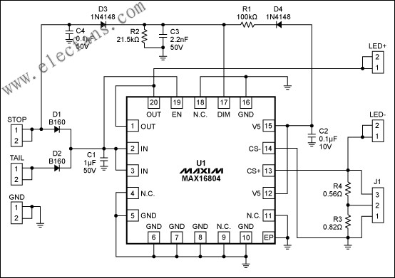
![]()
![]()
![]()
![]()