FTTH network increases the fiber density of the exchange
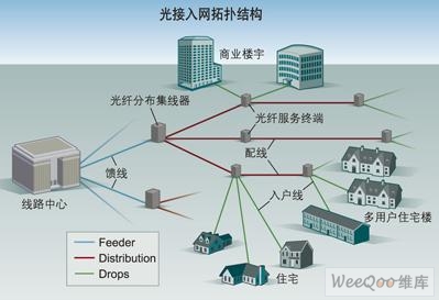
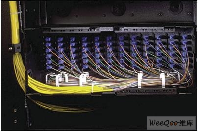
FTTH network increases the fiber density of the exchange First of all, why is there such a dramatic transition from pure optical transmission to complete fiber access? This is because service providers must be able to provide Internet access, digital TV and telephone services (often called "triple services") to attract and retain broadband users. Hybrid networks are usually limited by the transmission distance or the number of users on a single node. The fastest DSL network can only provide triple service from multiplexing equipment to the client within half a mile, while the bandwidth of the hybrid network is limited by the number of users of a single node and electrical noise, because electrical noise can damage the signal waveform. FTTH is the only all-optical access platform that can transparently, massively and reliably provide Gb / s rates in the service area. This is the fundamental reason for the transition to full fiber access. So, how should the optical fiber access network be designed? Centralized structure The best way to build an upgradeable FTTH network is to ensure that its physical layer can support multiple access structures. The centralized structure supports this aspect very well. This method of single fiber access to the user's home is widely used because of its high efficiency and ability to support multiple structures. PON is very common nowadays, and switched Ethernet or point-to-point networks are also applicable in certain situations. These situations refer to the place where the existing Ethernet infrastructure exists. Figure 1 shows the topology of an FTTH network, which contains three different optical cable parts: the blue line is the feeder section, the red line is the distribution section, and the green line is the household entry section. A typical optical access network topology: feeder (blue), wiring (red), and home line (green). In a FTTH network coverage area built with a centralized structure, there will be an optical fiber (red line in Figure 1) leading to the optical fiber service terminal to prepare to provide services for each home or enterprise. When the home or business needs to access the network, the home fiber (green line in Figure 1) can be immediately connected to the fiber service terminal to complete the fiber access service. So where does the upstream end of the distribution fiber (red wire) start? Each user's fiber can start either from the adjacent LCP splitter box or directly from the switching office. No matter which starting point can well support the future growth of bandwidth demand, that is, 100Mbit / s traffic per household. Based on this, the total cost of deploying a fiber optic network that supports all home users in the target area should be carefully considered. The total cost includes not only the cost of the optical cable, but the most important is the cost of laying the optical cable. Whether it is overhead or buried, the use of ribbon cable is most beneficial to improve efficiency and reduce installation costs. The following FTTH deployment example is to support thousands of home users with high efficiency, low cost, and high reliability in a fairly dense area. It utilizes ribbon optical cables, high-density switching office fiber optic hardware, and LCP splitter boxes. Photo 1. The high-density racks in the switching office can effectively support a large number of optical fibers, while also providing easy-to-operate manual failover recovery functions. A concrete example Figure 2 depicts the FTTH network structure of a city, where each region carries approximately 3450 users. In a switching office, a high-density rack can support up to 1728 fiber ports. In general, FTTH network designers prefer to use SC / APC connectors because its return loss can reach 65dB. A FTTH network structure based on the ring network can provide highly reliable services for a large number of users. There are several advantages of using SONET / SDH to carry Ethernet. First, it allows operators to use their existing TDM architecture to provide Ethernet. Second, in this scenario, Ethernet is another circuit provided, maintained, and managed by the TDM network, which is similar to other TDM services. On the other hand, using SONET / SDH to carry Ethernet also has some disadvantages. First, the cost of business increases due to the configuration, verification, and management of multi-layer protocols. Second, the available bandwidth is limited, usually within 1 ~ 8 T1 / E1 (if T1 is provided, the rate is 5 ~ 12Mbps). Third, since statistical multiplexing cannot be used, Ethernet services are as expensive as TDM services. The blue feeder ring network in Figure 2 may be composed of a tape-free optical cable containing 864 ITU G.652.D single-mode optical fibers. This ring network can surround the whole city and provide a manual failover mechanism. In this example, a rack can support up to 864 service ports and another 864 spare ports (216 lines per area). If the ring is cut, the jumpers in the affected area can be quickly and manually connected through the middle of the rack to the spare port on the other side. If there is no manual failover mechanism, then the city's ring service will be interrupted-until the disconnected line is reconnected, and such on-site maintenance is costly and time-consuming. It is worth mentioning that the use of ribbon optical cables can greatly reduce the time to terminate fiber in the switching office when constructing the network. By splicing 12 pairs of optical fibers at the same time, it takes only 3 people · days to complete the fusion of 1728 optical fibers in the exchange, while 14.5 people · days are required for each fusion of 1 pair of fibers. (Assume that it takes 10 minutes to splice 12 pairs of fibers at a time, and 4 minutes to splice 1 pair of fibers at a time). Photo 1 shows a high-density rack and its components, including a 72-port module slot, which can be gradually added as needed. Each pluggable module contains 12 fiber ports. In a transparent pluggable module, a 12-core ribbon pigtail is fused to the 12-core ribbon cable at the feeder end, and it usually takes only 10 minutes. This transparent plastic structure makes it very fast to locate the end of a jumper. And, if the service area is relatively small, you can directly connect home users to the central office rack without using the LCP splitter box in this example, then this module slot can accommodate three 32-port splitter modules . In addition, WDM modules often need to superimpose external video signals on PON signals. Pluggable modules can also implement this function when necessary. For the rack itself, slack jumpers can be conveniently placed in the center of the rack, so the extra jumpers are also easy to manage. Return to the example of FTTH network deployment in Figure 2. At each of the four crossover points (indicated by "X" in the figure), 216 fibers with a feeder ring are fused to four 144-port pre-terminated jumper boards (Photo 2). Photo 2. Pre-terminated jumper board. There are three other 144-port pre-terminated jumper boards in the cross-connect box, and 216 distribution fibers in the 864-core distribution ring cable (red part in the figure) are fused to it. In fact, this optical cable acts as both a feeder and a wiring. The first 216 optical fibers are connected to the feeder end in the LCP splitter box, and the remaining 57 * × 144) optical fibers serve as the wiring emitted from each LCP splitter box. Each distribution ring (red part in the figure) can have up to 6 LCP splitter boxes, and because each LCP splitter box can carry 576 users, the distribution ring in each area can carry a total of 3456 Users, the total carrying capacity of the four areas served is equal to 13,824 users. To serve so many users, only 864 ports in a rack are enough. The wiring ring also has a manual failover mechanism in case the cable is cut. When necessary, the jumper of the affected port can be manually connected to the other side of the distribution ring. Each LCP splitter box in the area has 18 optical fibers to be returned to the switching office to support 1 × 32 split ratio PON. Considering further, in the future, 18 more optical fibers can be added to support a 1 × 16 split ratio PON to provide more user bandwidth. In addition, these 36 fibers can be manually switched over by cross-connecting the jumpers in the box and the redundant feeder ports in the LCP splitter box. As for the 576 optical fibers from each LCP splitter box, if the distribution ring is cut, only some of the distribution box's customer service will be temporarily affected, and the service will not be restored until the distribution ring is re-spliced. One of the main advantages of the feeder ring and distribution ring is that the entire optical cable can be put into a 1.25-inch pipe or an overhead signal cable. The ribbon optical cable terminal distribution system and access terminal box can be inserted into the distribution optical cable along either side of the distribution ring. Then there are 4 to 12 subscriber lines on the pre-terminated terminal, which can be accessed into the pre-terminated fiber optic cable. income Today's optical access network requires that the optical fiber hardware of the switching office can be integrated with external optical cables and optical fiber hardware in a coordinated manner, which must not only facilitate operation and maintenance, but also reduce installation costs. Using a centralized structure and a high-density rack can improve the benefits of tape-free optical cables, because 12 optical fibers can be fused together in a pluggable module without the need for additional internal or external space in the rack. Without this space-saving design, some exchanges will not have enough space to accommodate all the fiber optic cables in the area. In short, the correct design improves the performance of the FTTH network in a special environment, and facilitates the upgrade of bandwidth and the replacement of transmission equipment in the future. Cassava Dregs Separator,Cassava Processing Machine,Cassava Processing Equipment,Cassava Milling Machine Hunan Furui Mechanical and Electrical Equipment Manufacturing Co., Ltd. , https://www.thresher.nl