Stepping motor motion law and speed control method
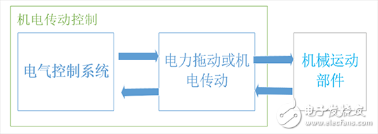
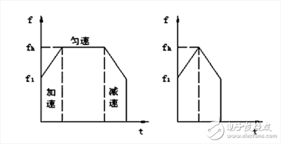
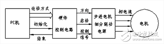
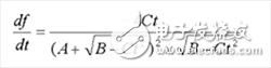
Electromechanical transmission control is the knowledge required by mechatronics talents. Since electric drive control devices and mechanical equipment are an inseparable whole, we can understand the general knowledge of electromechanical transmission control, and master the work of electric motors, electrical appliances, thyristors, etc. Principles, characteristics, applications, and methods of choice. Learn about the latest control technology in mechanical equipment. In modern industry, electromechanical transmissions not only include the electric motor that drives the production machinery, but also a complete set of controls for controlling the electric motor to meet the requirements of the automation of the production process. That is to say, modern electromechanical transmissions are associated with automatic control systems consisting of various control elements. The electromechanical system can generally be divided into three parts as shown in Figure 1. Figure 1 Electromechanical transmission control Before I went to this class, I thought that the electric motors were those DC motors that were high school, that is, the energized coils were rotating in the magnetic field. That is the DC motor. Slowly I touched the AC motor and I just started to know the 220V mains. I remember that during the semester, we worked as an intern, and saw so many lathes, milling machines, and drill presses under the engineering training... Because of the large power, the main motor is 380V. After finishing this door, I will learn more about their internal structure and working principle. It also shows that knowledge is a process of accumulating slowly. See more learning. I understand a lot of previous doubts. Seeing the intelligent robots on the TV, their activities are as comfortable as the bionic muscles. Especially Japanese robots. Its robotic arm is most likely controlled by a stepper motor, and another term is hydraulic and pneumatic. I think both have it. Fortunately, I entered the second class in the first day, learned something in it, and also touched the stepper motor. I bought one at the time of learning 51 MCU, and I felt very amazing. In addition to participating in the Jiangxi Electronic Design Competition a few days ago, I felt that if you want to choose the topic of control, stepper motor can not be less. So stepper motor is a good thing. I checked the information on the Internet. In the last century, there was a stepping motor. It is an electromagnet that can be freely rotated. The principle of action is no different from today's reactive stepping motor. It also relies on the air gap. Change to produce electromagnetic torque. Unfortunately, it was invented by foreigners. I started to write the topic. After finishing this class, the stepper motor made me obsessed. The stepper motor has an excellent role in position control, speed and control, which is unmatched by other motors. A stepping motor is an open-loop control element stepping motor that converts an electrical pulse signal into an angular displacement or a linear displacement. In the case of non-overload, the speed and stop position of the motor depend only on the frequency of the pulse signal and the number of pulses, and are not affected by the load change. When the stepper driver receives a pulse signal, it drives the stepper motor. The set direction is rotated by a fixed angle called the "step angle" whose rotation is performed step by step at a fixed angle. The angular displacement can be controlled by controlling the number of pulses to achieve the purpose of accurate positioning. At the same time, the speed and acceleration of the motor rotation can be controlled by controlling the pulse frequency, thereby achieving the purpose of speed regulation. The main features of the stepper motor are as follows: (1) The speed and step value are not affected by voltage fluctuations, load changes and temperature changes. They are only synchronized with the pulse frequency. The total displacement of the rotor motion depends only on the total number of pulse signals. (2) Open-loop control, no feedback, the system structure is greatly simplified, the work is more reliable, the maintenance is more convenient, and the accuracy is high enough in the general positioning drive device. (3) The control performance is good, the speed of the motor can be adjusted by changing the frequency of the pulse in a wide range, and the braking, reverse and any other changes in the operation mode are all completed in a few pulses. (4) The error does not accumulate. There is always a certain error between the angle and the theoretical value of the stepping motor. However, it has a fixed number of steps per revolution, so the step error will not be lost without losing the step. accumulated. The biggest characteristic of the stepping motor is that it can accept the digital control signal (electric pulse signal) and convert it into the corresponding angular displacement or linear displacement, so it is an actuator that completes the digital analog conversion. . Moreover, it can perform open loop position control, and input a pulse signal to obtain a specified position increment. Compared with the conventional DC servo system, such an incremental position control system has a significantly reduced cost, and it is almost unnecessary to perform system adjustment. Therefore, stepper motors are widely used in CNC machine tools, robots, remote control, aerospace and other fields, especially the development of microcomputers and microelectronics technology, making stepper motors more widely used. Speed ​​characteristics of stepper motors The speed of the stepper motor depends on the pulse frequency, the number of rotor teeth and the number of beats. Its angular velocity is proportional to the pulse frequency and is synchronized with the pulse in time. Therefore, in the case where the number of teeth of the rotor and the number of running beats are constant, the required speed can be obtained by controlling the pulse frequency. Since the stepper motor is started by its synchronous torque, the starting frequency is not high in order to avoid out-of-step. In particular, as the power increases, the diameter of the rotor increases, the inertia increases, and the starting frequency and the maximum operating frequency may differ by a factor of 10. In order to give full play to the fast performance of the motor, the motor is usually started below the starting frequency, and then the pulse frequency is gradually increased until the desired speed. The selected rate of change is such that the motor does not lose synchronization and the startup acceleration time is minimized. In order to ensure the positioning accuracy of the motor, the motor must be gradually reduced from the highest speed to a speed that can be stopped (equal to or slightly greater than the starting speed) before stopping. Therefore, when the stepping motor drags the load at a high speed and is positioned at a high speed, it generally includes five stages of “start-acceleration-high-speed operation (constant speed)-deceleration-stopâ€. The speed characteristic is usually trapezoidal if moving. The short distance is the triangular velocity characteristic, as shown in Figure 2. Figure 2 Speed ​​curve of stepper motor Stepper motor control system structure At the appropriate time, the PC sets the initial value of the 8253 counter 0 on the hardware control circuit, and sets the frequency change (ie, speed and acceleration change) during acceleration and deceleration to prevent out-of-synchronization. For example, set the speed graph in the point control. When starting and raising the speed, the stepping motor generates enough torque to drive the load to keep up with the specified speed and acceleration. When decelerating, the falling characteristic makes the load not generated. Overshoot, stop at the specified position. The 8253 on the hardware control circuit board generates a pulse square wave as the interrupt signal source, starts the solidification program in the subdivision drive circuit to generate a pulse of a certain frequency, and drives the step motor movement after power amplification. The change of the moving direction of the stepping motor and the starting and stopping are realized by the computer control hardware control circuit. Figure 3 stepper motor control system The combination of software and hardware is controlled, and has the advantages of simple circuit and convenient control. In this kind of control, the microcomputer software occupies less storage units, and the program development is not limited by timing. As long as the external interrupt is allowed, the microcomputer can freely perform other tasks between each step of the motor to realize the motion control of multiple stepping motors. Determination of the initial value of the timer The real-time control of the stepper motor uses the PC. The pulse square wave is generated by the 8253 timer. The counter 0 works in mode 0 to generate the pulse square wave. The counter 1 works in mode 1 and the clock frequency of the 8253 counter 0. Provided by a 2MHz crystal. If the initial value of the counter assigned to the 8253 counter 0 is D1, the generated square wave frequency is f1=f0/D1, the period T1=1/f1=D1/f0, and D1=f0T1=f0/f1. Where f1 is the starting frequency and f0 is the crystal frequency. Mathematical model of stepping motor lifting speed In order to prevent the stepping motor from running out of step, it is generally required that the maximum operating frequency should be less than (or equal to) the step response frequency fs. At this frequency, the stepper motor can be started, stopped or reversed without any loss of step. There are two driving modes for stepping motor speed-up, namely triangular and trapezoidal driving (see Figure 1), and the triangular driving method is a special case of trapezoidal driving, so we only need to study the trapezoidal mode. The acceleration and deceleration of the motor is achieved by the computer constantly modifying the initial value of the timer. In the motor acceleration phase, starting from the start-up instant, each time a pulse is generated, the initial value of the timer is decreased by a certain value, and the corresponding pulse period is decreased, that is, the pulse frequency is increased; in the deceleration phase, the initial value of the timer is continuously increased, The corresponding pulse period increases, the pulse frequency decreases, and the deceleration phase corresponds to the trapezoidal pulse frequency characteristic. The key to this design is to determine the pulse timing tn, which is the pulse period Tn and the pulse frequency fn. Assume that the number of pulses is calculated from the start of the instant, the number of pulses in the acceleration phase is n, and the start instant is the start of the count, the initial value of the timer is D1, and the decrease of the initial value of the timer is Δ. From the physical process of the acceleration phase, the first pulse period, that is, the pulse period T1 at the start-up, D1/f0, t1=0. Due to the modification of the initial value of the timer, the second pulse period T2=(D1-â–³)/f0=T1-â–³/f0, and the pulse timing t2=T1, the period of the nth pulse is: Tn=T1-(n-1)â–³/f0 (1) The pulse timing is: (2) The pulse frequency is: 1/fn=Tn=T1-(n-1)â–³/f0 (3) The above equation shows the relationship between the pulse number n and the pulse frequency fn and time tn, respectively. Let â–³/f0=δ, that is, the decrement of the adjacent two pulse periods in the acceleration phase, then the above formula is simplified as: Tn=(n-1)T1-(n-2)(n-1)δ/2 (4) 1/fn=T1-(n-1)δ (5) Simultaneously (4), (5), and simplify the relationship between fn and tn, the mathematical model of the acceleration phase is: Among them, it is a constant, and its value is related to the initial value of the timer and the amount of change in the timer, A=-δ, B=(2T1+δ)2, C=8δ. The change in pulse frequency during the acceleration phase is: (7) Oil-immersed Distribution Transformer, its HV level is 20kV, LV is 400V, its capacity is 2500kVA and below. Generally installed on the pole or in the distribution room, for lighting or power supply, three-phase power supply, fully sealed tank structure, to ensure the transformer safe and reliable operation. 20Kv Transformer,20Kv Distribution Transformer,20Kv Oil Immersed Transformer,High Quality 20Kv Transformer Hangzhou Qiantang River Electric Group Co., Ltd.(QRE) , https://www.qretransformer.com