Design of Video and Audio Collector Based on DM642
Design of Video and Audio Collector Based on DM642 In order to address these application requirements, this paper proposes an integrated data acquisition transmitter for video, audio and positioning information. This collector can not only provide a more natural, more realistic, and more timely geographic information system environment through live webcasting, the collected data can provide material for the construction of real maps and 3D scene maps, and can also realize video and audio based on positioning information Data segmentation and retrieval. 1 Overall system solution In order to achieve the high-quality positioning video and audio compression collection of the collector, real-time positioning video and audio transmission, and low power consumption and portability, the system uses TI's TMS320DM642 as the main control chip of the collector. DM642 is a high-performance fixed-point DSP in the TMS320C6000 family dedicated to multimedia applications launched by TI. It has 8 parallel operators, 3 dedicated video and 2 audio multiplexing interfaces, and integrates 10 / 100Mbit / s Ethernet MAC. These advantages of the chip are very suitable for the collection, compression and transmission of video and audio information. Figure 1 shows the hardware block diagram of the collector. GPS positioning data is read in by the TL16C752B through the serial port; the audio signal is quantized and sampled by the TLV320A IC23B at 8 kH z, 16 bits; the video signal is collected by the TVP5150. The positioning data that enters DM642 is encoded by H.264 video encoding at a low bit rate and synchronously synthesized with the audio encoding signal of G. 723, and then sent to a remote server through a wireless network. The other channel is encoded at a high bit rate and stored to 2.5 inches. hard disk. 2 System hardware design 2. 1 Video signal collection The video signal acquisition is shown in Figure 2. SCLK is the clock, GPCL is the enable signal, and Yout is the 8-bit BT.656 signal. In the system, the VP0 of DM642 is configured as VP0A + McASP mode, of which VP0A is configured as 8-bit BT. 656 video input, which is used to connect one video input. TVP5150PBS is a high-performance video encoder that converts the NTSC / PAL analog signal output from the video signal analog camera into a digital color-difference signal (YUV4: 2: 2). The output format is ITU-R BT. 656. 2. 2 Audio signal collection Figure 3 is the audio input block diagram, BCLK is the bit clock, LRC IN and LRCOUT are the frame synchronization input and output, and D IN and DOU are the audio input and output, respectively. McASP is simultaneously connected to 4 audio inputs and outputs. McASP is set to burst frame synchronization mode in the system. TLC320A IC23B is an audio encoding device that supports microphone, stereo input and stereo output. According to the requirements of G.723 encoding, the electrical signal input by the microphone is 8 K sampled by TLC320A IC23B and 16-bit quantized. TLC320A IC23B uses DSP mode to exchange data with McASP. 2. 3 GPS signal acquisition Figure 4 is a block diagram of GPS signal acquisition. TX and RX are serial data sending and receiving signals, respectively. TL16C752B adopts 8-bit asynchronous walking memory interface, supports baud rate up to 1 Mbyte / s, connects with DM642's external memory EM IFA, address A 2 A0 is used to address 8 registers of TL16C752B. The MAX3160 is a multi-protocol transceiver that can configure the serial port interface level to various interface level standards such as RS232 / RS422 / RS485. The GPS acquisition module adopts Ho lux M-89, which has a sensitivity of 159 dBm and supports the NMEA0183 data communication protocol. Its positioning accuracy is less than 3 m, which is higher than that of the S iRF chip. Wait for low speed positioning. 2. 4 Network data transmission The network data transmission connection diagram is shown in Figure 5. The network interface of DM642 is multiplexed with PCI and HPI. B3 and B10 in the system via PCI bus are configured as HPI16 + Ethernet interfaces. The Ethernet interface is composed of two parts: EMAC (data path of the network) and MD IO (state and control interface of EMAC). The system uses BCM5221 from Broadcom as the transceiver (physical layer) of 10 / 100M Ethernet. To achieve wireless network transmission, a 3G router and wireless network card are used to transmit data through the EVDO network. The 3G router uses Tenda's 3G611R, which is compatible with three 3G networks: EVDO, HSPA, and TD HSDPA. The wireless network card adopts ZTE's AC2746. The card supports downlink 3.1 Mbit / s and uplink 1.8 Mbit / s. Usually,10 & 20 layers PCB are HDI board,but some are not .Some with big trace width and space,holes are over 0.3mm too. We have much experience in doing 10 Layer PCB & 20 layer PCB. 10 Layer PCB 10 layer PCB 10 layer TG170 PCB 10 layer design Storm Circuit Technology Ltd , https://www.stormpcb.com
The wide application of geographic information system (GIS) and global positioning system (GPS) makes people enjoy many conveniences brought by location-based services. Traditional GIS is based on maps as the main method of visualization. However, 70% of human access to information comes from vision. Therefore, the organic integration of geographic location information and video information can excellently enrich the content of GIS and produce many new applications. Sites such as Microsoft ’s Windows Local Live and Image City Wuhan have launched live maps one after another, allowing people to understand each city intuitively, comprehensively and conveniently on the Internet. The combination of GPS information and video information is also conducive to 3D modeling of geographic information systems. For example, the 3DV ideoG IS software launched by the Iwagen Research Institute in Japan can automatically generate panoramic video images with positioning information taken on land and in the air. Corresponding highly realistic 3D scene model. 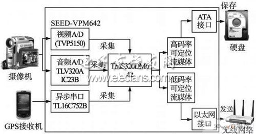
Figure 1 Collector hardware block diagram 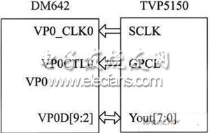
Figure 2 Block diagram of video acquisition hardware. 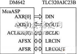
Figure 3 Audio acquisition hardware block diagram. 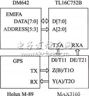
Figure 4 GPS acquisition hardware block diagram. 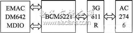
Figure 5 Network transmission hardware block diagram
A ten-layer board should be used when six routing layers are required. Ten-layer boards, therefore, usually have six signal layers and four planes. Having more than six signal layers on a ten-layer board is not recommended. Ten-layers is also the largest number of layers that can usually be conveniently fabricated in a 0.062" thick board. Occasionally you will see a twelve-layer board fabricated as a 0.062" thick board, but the number of fabricators capable of producing it are limited..
High layer count boards (ten +) require thin dielectrics (typically 0.006" or less on a 0.062" thick board) and therefore they automatically have tight coupling between layers. When properly stacked and routed they can meet all of our objectives and will have excellent EMC performance and signal integrity.
A very common and nearly ideal stack-up for a ten-layer board is shown in Figure 12. The reason that this stack-up has such good performance is the tight coupling of the signal and return planes, the shielding of the high-speed signal layers, the existence of multiple ground planes, as well as a tightly coupled power/ground plane pair in the center of the board. High-speed signals normally would be routed on the signal layers buried between planes (layers 3-4 and 7-8 in this case).