How to realize the design and research of DMA transmission in S5935
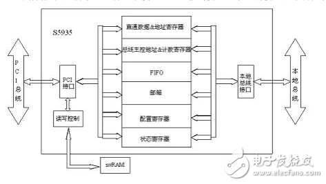
Abstract : This paper introduces the basic structure of the S5935, a dedicated interface chip with PCI bus master function. It explains how it implements the functions of the DMA controller and gives the WDM driver for DMA transfer. There are three transmission methods between the computer and the peripheral: program mode, interrupt mode, DMA (DirectMemoryAccess) mode. Among them, the first two methods are that the CPU realizes the data transmission between the host and the peripheral by executing the instruction, and the transmission speed is low; the latter way is that the DMA controller directly realizes the data transmission between the peripheral and the memory, The transmission speed is higher without going through the CPU. Therefore, in high-speed data transmission systems, DMA is often used to implement data transmission between computers and peripherals. Because the PCI bus in the personal computer has the characteristics supported by the bus master device (the bus master device supports the full support of the PCI bus master device, allowing the same level of PCI bus access and accessing the main memory and the expansion bus through the PCI-PCI and the extended bus bridge. The device, and the PCI master can access the target residing on another PCI bus at a lower bus level). Therefore, there are two ways to implement DMA transfer. One is to use the DMA controller inside the computer; the other is to use the PCI interface chip with bus master function. Since the latter approach does not occupy the DMA channel of the computer system, the resources of the computer are saved, and therefore, it is used more. There are two main types of PCI interface chips with bus master functions: one is a programmable logic device that can be embedded in an IP core, such as the Sparten series of Xilinx, and the other is a dedicated PCI bridge chip, such as PCI9054 and AMCC of PLX. The company's S5935 and other products. The former design is more flexible, but requires developers to have a deeper understanding of the PCI specification, the development cycle is longer; the latter design is relatively simple, developers only need to correctly configure the configuration space of the interface chip, pay attention to the electrical connection specification of the pin, you can Proper use, shorter development cycle. This article takes the dedicated PCI interface chip - S5935 as an example to introduce how to implement DMA transmission when it is used as the PCI bus master. S5935 is one of AMCC's S59XX series interface chips. The chip is powerful and can be used for high-speed data acquisition cards, video acceleration cards, multimedia communications, etc. It can be used as both a PCI bus master device and a PCI bus slave device, and is widely used. It has three working methods: MAILBOX (mailbox) working mode, PASS-THRU (straight-through) working mode, FIFO (first in, first out) working mode. The first two working modes can only be the working mode of S5935 as the PCI bus slave device. The FIFO working mode can be the working mode of S5935 as the PCI bus master device, or it can be the working mode of S5935 as the PCI bus slave device. The structure of the S5935 is shown in Figure 1. It has three interfaces: PCI bus interface, local interface and non-volatile storage. Figure 1S5935 block diagram Interface. The PCI interface is used to transfer data, addresses, commands, etc. between the computer and the S5935. The local interface is used to transfer data between the S5935 and the external memory and to transfer addresses, commands, etc. to the external control logic. There are two types of non-volatile memory interfaces, which can be connected to serial nvRAM or to byte nvRAM for S5935 header space configuration. The configuration space of the S5935 has 256 bytes and is divided into a header configuration space and an operation register space. The header occupies 64 bytes, which can be divided into two parts. The definition of the first 16 bytes is the same in all types of devices, such as vendor code VID, device code DID, and the remaining 48 bytes. Different settings are made according to the basic functions supported by the device, such as the setting of the interrupt pin, the size setting of the PASS-THRU mapping in the memory or I/O space, and the base address setting of the PCI operation register. The operation register is divided into a 16-word PCI operation register and a 18-word local operation register. The former can only be accessed through the PCI bus, while the latter can only be accessed through the local bus. Their structure is very similar, the main difference is that the local operation register has two more pass-through address registers (APTA) and a straight-through data register (APTD) for the through mode of operation than the PCI operation register, and one less master register (MCSR). The FIFO mode of the S5935 can work in the bus master mode. At this time, the S5935 is equivalent to a DMA controller with a data buffer, which can perform DMA transfer without occupying the DMA channel of the computer system. Its internal structure is shown in Figure 2. It has two unidirectional FIFOs: one FIFO data transmission direction is from PCI bus to local bus, and the other is used for local bus to PCI bus data transmission. The size of each FIFO is 8&TImes; 32bit; There are also two address registers and two data registers for storing the first address of the DMA transfer and the number of bytes required for the transfer. The DMA transfer of S5935 can be set to be initiated by the local bus or by the PCI bus. It is implemented by setting bit 7 of the 45h unit of nvRAM during initialization. Let's take the DMA transfer initiated by the PCI bus as an example to introduce the DMA controller features of the S5935: When DMA transfer is required, the driver sends a DMA request signal to S5935 by setting bit 14 or bit10 of the MCSR register (the former is used for computer internal memory read and the latter is used for internal memory write). S5935 is satisfied according to the FIFO management scheme. Condition, enable REQ# signal, apply for bus control. When the bus arbiter receives the bus control request signal, if enabled, the GNT# signal is enabled, thereby transferring control of the bus to S5935. After the S5935 gains control of the bus, the address signal stored in the MWAR (or MRAR) is sent to the PCI address bus, and each time a byte is transmitted, the address in the MWAR (or MRAR) is automatically updated to point to the next one. The byte to be transferred. S5935 sends a read/write control signal through C/BE[3:0]#. For example, if the transmission is 0110, it is the internal memory read, and the transmission is 0111, which is the internal memory write. In order to determine the number of bytes transferred, and to determine whether the DMA transfer is over, S5935 uses MWTC (or MRTC) to store the number of bytes to be transferred. For every 1 byte transferred, the value of the byte counter is automatically decremented by 1 to At 0, the DMA process ends. Pool Water Pump,Pump Swimming Pool,Dc Pool Pump Motor,Dc Brush Solar Pump Wuxi Doton Power , https://www.dotonpower.com