The working principle and peripheral hardware interface of AMBE-1000 voice compression chip
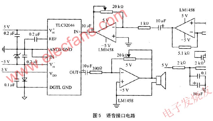
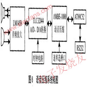
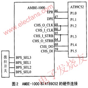
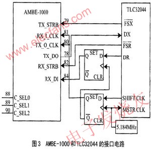
AMBE is a low bit rate, high quality speech compression algorithm based on MBE technology. It has the advantages of good voice quality and low coding baud rate, and is embedded in DVSI's AMBE-1000 voice compression chip. The chip is a high-performance multi-rate speech encoding/decoding chip with a speech encoding/decoding rate between 2400 and 9600 b/s, varying at 50 b intervals. There are independent speech coding and decoding channels inside the chip, which can complete the encoding and decoding tasks of the speech at the same time; and all the encoding and decoding operations are completed inside the chip, and no external memory is needed. These features of the AMBE-1000 make it ideal for digital voice communications, encrypted voice communications, and other applications where digital processing of voice is required. This article refers to the address: http:// 2 AMBE-1000 working principle and hardware interface 2.1 Basic workflow Simply put, the working process of AMBE-1000 is shown in Figure 1. The AMBE-1000 can be viewed as consisting of two separate encoders and decoders. The encoder receives an 8 kHz speech data sample stream (such as 16-bit linear, 8-bit A-law or 8-bit U-law) and outputs a channel data stream of a desired baud rate. Instead, the decoder receives a stream of channel data and synthesizes a stream of voice data. The interface timing of the encoder and decoder of the AMBE-1000 is completely asynchronous.    2.2 channel interface The channel interface is used to describe the compressed bit stream output from the encoder and the compressed bit stream input to the decoder. The interface can also output status information, such as whether a dual tone multi-frequency (DTMF) voice signal input can be detected. In addition, the interface performs more complex control operations on the encoder/decoder (usually at initialization). These control functions include the choice of voice and error correction code speed, and the A/DD/A chip device. In most voice transmission systems, the actual coded bit stream is extracted from the channel in a certain format, and combined with the system information to form a system transmission data stream, which is transmitted through the transmission channel; is extracted at the receiving end, and passes through the decoder. The data stream that constitutes the format required by AMBE-1000. The AMBE-1000 has multiple modes of operation: parallel and serial, framed and frameless, active and passive. Among them, the parallel passive frame mode is the most flexible and practical working mode. The corresponding operating mode can be selected by connecting the pull-up resistor and the dial switch to the corresponding interface select pin. By adopting the above method, the speech rate and the error correction code rate can be freely selected between 2400 to 9600 b/s and 50 to 4750 b/s by the selection switch. In serial active mode, the operating clock of the AMBE-1000 is 27MHz, and the clock of CHS_O_CLK is 4.5MHz (27MHz/6), that is, 1 bit of data needs to be read within 0.22μs. Even if the MCU works at 24MHz, it cannot read the data, so it must be passive, so you can set the CHS_O_CLK clock yourself. The clock also needs to be able to read 34 bytes of data in 20ms (ie 1 frame). Data); At the same time, the parallel port occupies more interface resources, so the serial passive frame mode is adopted, and its hardware connection is as shown in FIG. 2.    AMBE-1000 requires A/D, D/A voice data and serial input and output. The key of the interface circuit is the frame synchronization of voice data, and its hardware interface circuit is shown in FIG. Among them, 5.184MHz is used as the working clock of TLC32044, and also used as the trigger pulse of D flip-flop. The shift pulse (SHIFT CLK) generated by TLC32044 is used to implement synchronous transmission of bits. The TLC32044 chip is selected by setting C_SEL0-2 to 010.     2.5 clock and reset The working clock of the AMBE-1000 is 26 to 30 MHz. It has three input modes: TTL clock source direct input, CMOS clock source or oscillator direct input, and crystal oscillator circuit input. In this system, the clock is input using a crystal oscillator circuit. The active reset signal is low and must last for more than 6 clock cycles. 3 peripheral interface circuit 3.1 How does TLC32044 work? The digital processing of voice signals is indispensable for A/D and D/A conversion of voice signals. In this design, a 14-bit dynamically adjustable high-precision programmable A/D, D/A TLC32044 chip produced by American TI Company was selected. As shown in FIG. 4, the TLC32044 is composed of an anti-aliasing input filter, an A/D, a D/A, an output reconstruction filter, and the like. The separation of analog and digital ground, analog and digital power supplies reduces noise and guarantees a wide dynamic range. The analog circuit section uses a differential circuit to minimize noise. TLC32044 also has programmable sampling frequency. Its sampling frequency can be controlled by software in the range of 7.2kHz~19.2kHz. It can work in four working states: synchronous word, byte transfer and asynchronous word and byte transfer, respectively. Word or 8-bit serial serial communication, with a maximum conversion accuracy of 14 bits, only need to provide a 5.184MHz clock externally to work. The chip can be programmed to accommodate two analog signal inputs simultaneously. After the system is powered on (or reset), it works according to its default working mode, that is, 16-bit word or 8-bit byte serial communication mode, with a maximum conversion accuracy of 14 bits, and only needs to provide a 5.184MHz clock externally to work. The chip can be programmed to accommodate two analog signal inputs simultaneously. After the system is powered on (or reset), it works according to its default working mode, that is, serial communication is synchronized by 16-bit words, and the sampling frequency is 8 kHz. To change the state of the TLC32044, the control word can be programmed into the TLC32044 via the DX pin.    3.2 TLC32044 peripheral interface circuit In order to realize the voice input and output of the system and ensure the effective gain, the input and output voice signals must be amplified. The circuit is shown in Figure 5. In this system, the high-performance, low-noise LM1458 amplifier is used to adjust the gain of the input and output speech signals through a 20kΩ adjustable potentiometer. In this circuit, a -5V power supply is required, and the general circuit only provides a +5V power supply. Therefore, the MAX660 chip is used in the circuit design to realize the conversion of the +5V to -5V power supply. In this way, the entire circuit can be powered from a single power source.     System analysis The block diagram of the voice compression system is shown in Figure 6. The system can choose the working rate independently. In serial active framing mode. The serial input and output pins of the AMBE-1000 can be shorted to each other for system self-test to confirm whether the system is normal. In the system design, attention must be paid to the distinction between analog ground and digital ground to avoid the introduction of background noise. The circuit design has been applied to the end voice compression of the intelligent communication terminal, which can reduce the amount of data of the voice and increase the confidentiality of the voice. The circuit can also be used in solid-state interviewers, with the addition of a rewritable Flash chip and control buttons.    BBQ Grill,Fashion Barbecue Grill,Stainless Steel Grill,Smokeless BBQ Grill Shaoxing Haoda Electrical Appliance Co.,Ltd , https://www.hotplates.nl
2.3 Data format
The AMBE-1000 data consists of 17 words per frame in a frame format. The encoder outputs 17 words every 20ms, while the decoder receives 17 words. The first 5 words of each frame are composed of a frame header (Header), an identification flag (ID), a status (output), or control (input) information, and the remaining 12 words constitute encoded/decoded data. A total of 192 bits of these 12 words are the maximum data rate (192b/frame x 50 frames/s=9600b/s) at which the AMBE-1000 operates in the 9600b/s mode. When the encoded/decoded data rate is lower than 9600 b/s, the insufficient bits are complemented by zero. It should be noted that regardless of the rate at which the AMBE-1000 operates, all 272 bits (17 words x 16b = 272b) of frame data (including any unused trailing zeros) must be output from the encoder or input to the decoder. The frameless format can only be used in serial mode.

The D1 and D0 bits in the DR timing are empty, and the effective precision of the A/D conversion is D15 to D2; and the D1 and D0 bits in the DX timing are used as control bits. The FSR and FSX are the receive and transmit frame sync signals, respectively, at 8 kHz. In synchronous mode, the two are identical.