Mask and crystal circular appearance effects in optical lithography and EUV lithography
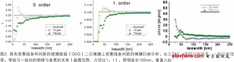
Advances in miniaturization in semiconductor fabrication have led to an ever-increasing lithography mask and geometry on wafers. Accurately simulating the diffraction produced by these patterns requires the use of precise electromagnetic field (EMF) simulation methods. These methods solve the Maxwell's equations with appropriate numerical methods for a given geometry, material parameters, and incident field (illumination) conditions. The finite difference time domain method (FDTD) uses the discrete integral format for the differential form of Maxwell's equations. This method is very flexible and easy to adapt to a variety of different geometries and incident field conditions. The calculation results and accuracy of this method mainly depend on the degree of spatial discretization based on the number of grid points per wavelength (GPW). The calculation time and storage requirements are linearly proportional to the total number of grid points in the simulation. In many cases, 15-25 GPW is sufficient to obtain an intuitive near-field map and qualitative study of certain phenomena. Typical accuracy requirements for lithography simulations require more than 100 GPW. FDTD has been applied to solve many typical problems in advanced lithography. Like the waveguide method (WGM) and the rigorous coupled wave analysis (RCWA), the modal method is also a Fourier expansion method that uses the cutting simulation body, the electromagnetic field and the optical material characteristics in the slice, and the coupling of the Fourier coefficient between them to solve the Maxwell equation. The scattering field is obtained as a solution to the generated algebraic equation. The calculation results and accuracy of WGM (and similar methods) are mainly determined by the order of the Fourier expansion (WG order) and the number of slices. The calculation time and storage requirements increase with the cubic of the WG order. In general, these modal methods are very accurate and efficient for solving 2D problems (lines and isolation) with rectangular block structure geometries (such as vertical absorption sidewalls). The poor micronization capabilities of these methods make them difficult to apply to larger 3D problems (such as semi-dense matrices of contact holes). A special decomposition method has been developed to solve this problem. Efficient implementation of WGM is currently used for efficient simulation of optical and EUV masks and crystal dome effects. Other EMF simulation methods are based on integral expressions of Maxwell's equations. Recent papers have demonstrated extremely high accuracy for light diffraction, finite element method (FEM) and finite integral technique (FIT) for simulating complex-shaped mask geometries. This makes these methods very useful for calibrating other methods and simulations for special occasions. A detailed understanding and accurate simulation of light diffraction from lithographic masks and (sub)wavelength characterization on wafers is essential for developing and optimizing advanced lithography processes. Effect of mask morphology Mask model Figure 1 shows two essentially different simulation methods for light transmission through a photomask. In the Kirchhoff method (left), the amplitude and phase of the transmitted light are directly determined by the mask layout. For the binary mask shown, the transmitted light has an amplitude of 0.0 in the chrome-covered region and the remainder is 1.0. The phase of the transmitted light is constant. The precision mask model (right) calculates the amplitude and phase of the transmitted light using the numerical solution of Maxwell's equation. The diffraction spectrum in the far field of the mask is obtained by the near-field Fourier transform and is shown in the lower half of Fig. 1. The projection pupil of the lithographic imaging system covers a portion of the diffraction spectrum and converts it into a pattern on one side of the wafer. Typically, the mask is illuminated by different directions. The diffracted light of a particular illumination direction can be obtained in two ways: by using a precision EMF to simulate the associated incident light direction; or by angularly shifting (rotating) the diffraction spectrum of the direction of the incident light before calculation (Hopkins method). A precise EMF simulation of all relevant incident light directions (without the Hopkins method) is the most accurate and time consuming. Mask diffraction analysis Direct analysis of the mask diffraction spectrum or mask diffraction analysis can be used to identify the most important imaging results of the mask side scattering effect, the so-called mask topography effect. Figure 2 shows the simulated diffraction efficiencies of the zero-order and first-order diffracted lights of the normally incident light and the phase difference between these diffraction orders. Comparing the so-called thin mask or Kirchhoff method, the EMF simulation results show that the feature size of the mask and the polarization of the incident light have a significant influence on the intensity and phase of the diffracted light. The effect of feature size and polarization increases as the strip width decreases. For feature sizes below 80 nm, a significant mask-induced phase effect can be observed. These phase effects produce results such as aberrations.
To guarantee process quality control, Xunda has line leakage detecting system, line laser barcode system, Range Hoods appliances testing system, and apply finished product sample test, first article inspection and other complete spot testing systems.
Stainless steel+tempered glass
760m³/h air flow
3 speed electronic switch
6 layers washable aluminum grease filters
2x2LED lamps
Kitchen Range Hoods,Slim Hoods,Recirculating Range Hood,Stainless Steel Range Hood Xunda Science & Technology Group Co.ltd , https://www.xundatec.com