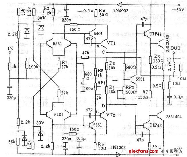
The eagle power amplifier circuit adopts a fully complementary symmetrical push-pull circuit, which has the advantages of stable performance and large dynamic range, and is low in price and solid in material quality, so it is valuable for its improvement. The FD-555 type amplifier used is better in sound quality, and the low frequency effect is also good. However, when listening to some deep bass songs, I still feel the sound is clearer and the underlying air is not enough. Therefore, it is decided to improve the voltage amplification stage circuit and improve it. The following circuit is shown below. That is, after the voltage amplification stage, VT1 and VT2 are added as the emitter output, and the composite amplifiers are combined with 5551 and 5401 respectively to improve the current output capability of the current stage. This is more stable and reasonable than using the three-stage Darlington tube in the output stage. In one fell swoop, the linearity of the circuit is increased and the first-order buffer is added. VT1, VT2 select medium power audio pair tube 2SD667, 2SA647, should be strictly selected pairing. When the stage is made to have good linearity, resistors R3 and R4 are added (7 to 10 kΩ is selected). Since there are fewer new components, it is not necessary to make a separate circuit board, which can be directly modified on the original circuit board. In the adjustment, first short the AC and BD points, adjust the RP2 to be larger, and measure the voltage across the push stages R6 and R7 to make it close to 0V to ensure the safety of the power amplifier tube, and then adjust the working level of the rear stage. (The side should be measured while calculating).
As known from Figure 1, the current of the input stage emitter resistor R1 is:
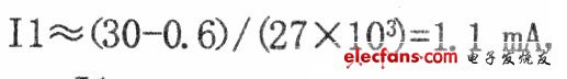
Then the current flowing through the load R2 is 0.55 mA. The voltage across it is U2 = 0.55 mA & TImes; 2.2 kΩ = 1.21 V, the voltage across R* is 1.21 VO. 6 V = 0.6 V, and the current flowing through R * is 0.6 V. /50Ω = 12mA. Then adjust RP1 to the minimum, disconnect the AC and BD, measure the voltage across R5, and adjust RP1 to make U旷4V, then IRS=4V/lkΩ=4mA, that is, the current of VT1 is 8mA, then measure again. The voltage of R* should be about 0.6V, which is basically unchanged. Then connect the multimeter to the two ends of the emitter resistor R8 (0.5Ω) of 2SC3858 and 2SA1494, and gradually reduce the RP2 to make the resistance drop to 50mV. It is bigger, but the heat dissipation measures must be in place. Finally, the drift voltage of the output terminal OUT should be less than 20mV. Otherwise, check the matching of the amplifier stage tube. Then connect 10Ω dummy load to observe for 30min, and it can be put into use without abnormal conditions.
Construction field, ships building industry, petroleum & chemical industries,
war and electricity industries, food processing and medical industry, boiler heat exchange, machinery and hardware fields. Stainless
steel pipe can be made according to the customers requirements.
Standard export
seaworthy or as per customers' requirement

We have imported machine for protecting the quality of products.

Copper Bar
Copper Bar,Flat Copper Bar,Oxygen Free Copper Bar,Electrical Application Copper Bar Flat
HENAN HUAYANG COPPER GROUP CO.,LTD , https://www.huaonwire.com