LCD TV design using MSTAR MST718BE
LCD TV design using MSTAR MST718BE As more and more electronic consumer manufacturers join the current increasingly prosperous LCD industry, the competition between the whole machine manufacturers is becoming more and more fierce. For an LCD TV, most of the LCD panel technology is used by Korean and Taiwanese companies. Monopoly, the room for change is very small, so for TV manufacturers who want to continue to maintain a leading position in the industry, the selection of new TV signal processing solutions is particularly critical. As a chip with video processing and LCD control functions, MST718BE / U can not only receive NTSC / PAL / SECAM CVBS and S-VIDEO video analog signals from TV tuner, DVD or VCR signal source, but also very good Support weak signals and non-standard signals. Its built-in line-buffer provides a 2D comb filter, in addition to a 10-bit dual-channel analog-to-digital converter, which can accept YPBPR and VGA signals. The output format supports 8-bit TTL and dual-channel 8-bit LVDS, and can support a display screen with a physical resolution of up to 1440 × 900. The following will discuss how hardware engineers should use MST718BE / U as the main chip, and with a small number of peripheral devices, build a powerful LCD TV signal processing platform. LCD TV platform architecture In the video processing circuit of the LCD TV platform, there is an IF (intermediate frequency) analog TV signal input to the LCD TV interface, and then to the LCD screen to display images. The front end needs to be demodulated by the high frequency head, and then output the CVBS video signal through the intermediate frequency amplifier. The video decoding, interlaced and progressive conversion, image effect adjustment, image scaling, LVDS / TTL output and other steps of the back end are all independently completed by MST718BE / U. Since the MST718BE / U has a built-in Line_buffer, for general applications, users do not need to use external storage. In addition, MST718 also has a built-in 8051 microprocessor, which can provide OSD (on-screen menu adjustment), and control peripheral devices through the I2C bus and GPIO port. It can meet most of the user interface and TV function requirements, so there is no need to add a microprocessor circuit outside. The audio processing part of the LCD TV platform requires an audio decoding chip to decode the output, and an audio power amplifier chip to output the signal to the speaker. The power amplifier chip can be selected by the TV manufacturer according to factors such as desired power requirements, sound effects and other factors. Figure 1 is a block diagram of an LCD TV platform system based on MST718BE / U. Design Points MST718BE / U adopts 128-pin PQFP package, which takes up less space and has lower requirements on the mounting process. Its system platform design can be completed by two-layer PCB, which has certain advantages in development cycle and cost. However, when designing the MST718BE / U peripheral circuit, the following issues should be noted. 1. Power Circuit MST718BE / U has three kinds of power pins with different input voltage values, with voltages of 2.5V, 3.3V and 5V, which are mainly used to supply power to each module inside the chip. These three voltages should be provided by a standby 5V power source that is not controlled by the standby, because this can ensure that after the chip is in standby, the program can still work normally in response to an external restart command. In practical applications, because the power of the standby 5V power supply is generally small, it is recommended to use a diode that can pass a larger current to connect to the 5V power supply for normal operation to ensure the continuous supply of current. In addition, it is recommended to parallel connect a 100nF filter capacitor on the power pin of MST718BE / U to minimize power ripple. Figure 2 shows the LDO application circuit diagram that provides power for the MST718BE / U chip. 2. Oscillator input The external 12MHz crystal oscillator signal is connected through the XTALin and XTALout pins. In MST718BE / U, all the required reference frequencies are obtained by dividing the external 12Mhz crystal oscillator signal. Two NPO capacitors connected across the crystal are used to reliably start the crystal and ensure the stability of the crystal frequency. The NPO capacitance value is determined by the crystal specifications. In the video decoder, in order to accurately demodulate the difference signal, the key is to restore the reference amplitude carrier Fsc at the same frequency and in phase with the transmitter at the receiving end, otherwise, the demodulated V component will contain the U component, The U component will contain a V component, resulting in abnormal colors, or even achromatic colors. Therefore, in the application process, it is necessary to ensure that the NPO capacitance matches the crystal specifications. 3. Reset circuit MST718BE / U has two sets of 5 reset pins, among which FB1 (pin 42) and FB2 (pin 39) are external reset pins. Normally, these two pins should be shorted together and connected to 1.2V. This 1.2V can be obtained from an external power supply. When the voltage on FB1 and FB2 is lower than 1.2V, the chip will reset. In practical applications, it is recommended to connect the output of the peripheral voltage regulator module (LDO) to 1.2V through a resistor divider and connect it to FB1 and FB2. It should be noted that when designing the circuit, a reservation should be made on different peripheral LDOs, so that the LDO with slow power-on can be selected according to the actual situation to ensure that the voltage on each power supply pin is stable when the chip is reset . Figure 3 is the actual reset circuit diagram. MST718BE / U's Powergood (Pin 44), Power_on_RStn (Pin 68), Reset (Pin 72) are internal reset pins, they provide reset to other modules inside the chip by the internal reset signal. Among them, Powergood and Power_on_RStn are connected together through a 75-ohm resistor. Power_on_RStn needs a 4.7K resistor to be connected to the GND near the chip, and Reset needs to be connected to the GND near the chip with a 1K resistor. The specific connection method is shown in Figure 4. 4. Connection of serial flash memory circuit The program running on the MST718BE / U TV platform is required to be written into an external serial flash memory chip PS25LV020. Mstar will provide the flash memory chip while providing the MST718BE / U chip, which will not only facilitate the use by TV manufacturers, but also ensure the stability of the cooperation between the MST718BE / U and the flash memory chip. The PS25LV020 has 256KB of storage space, which is sufficient for TV platforms whose functional requirements are not particularly complex. MST718BE / U reads data with PS25LV020 through a four-bit serial bus. The specific circuit is shown in Figure 5. Summary of this article Based on the LCD TV developed by MST718BE / U, it can be replaced with a pin-compatible chip for the needs of the European and American markets to make the product compatible with the requirements of the global market. Among them, MST718BE is developed for the European market, with graphics, Li Yin function; MST7181BU is developed for the US market, supports CCD and Vchip functions. Since Mstar has integrated these functions in the chip hardware DSP, developers can directly build their application layer on the existing basis and call it. For MST718BE / U, Mstar also provides a mature underlying software platform that can speed up the development of LCD TV software. It can be seen from the above description that it is not difficult to build a customized LCD TV signal processing platform. In order to further promote the research and development of LCD TVs, Mstar has now designed and provided an LCD platform demonstration board based on MST718BE / U, which can be used as a reference design and effect demonstration tool. The demo board is an LCD TV platform for the global market, which supports graphic and Liyin functions, and can also support CCD and Vchip functions by switching to pin-compatible chips of the same type. 38140 12Ah 3.2V Lithium Ion Battery Lithium Ion Battery Pack,Lithium Marine Batteries,Lithium Ion Polymer Battery,Black And Decker Lithium Battery Zhejiang Xinghai Energy Technology Co.,Ltd , https://www.headwayli-battery.com
In addition to lower cost, the two characteristics of high integration and compatibility of the main chip with the global market must be considered when choosing a solution. This is because the main chip's high integration and functional compatibility with the global market has the following advantages: (1) fewer peripheral devices, simple hardware design, can greatly shorten the development cycle, and help improve product reliability; (2) The function of the main chip is compatible with the global market, which provides convenience for machine manufacturers to derive other models, making the model development continuity. Therefore, the high integration and compatibility of the main chip in the global market will be the future development trend of LCD signal processing solutions.
The "high integration of the main chip" mentioned here means that the main chip has at least a microcontroller (MCU), a video signal decoder, an interlaced progressive conversion module, an analog-to-digital converter, an image scaling module, and is compatible with LVDS / TTL output Features. "Compatible global platform" means that the internal design of the IC must take into account the needs of the European and American markets, so that the designer can change the DSP code according to different market needs, so that the product has the Teletext and Li Audio functions, as well as CCD and Vchip functions required by the US market.
The MST718BE chip introduced by Mstar Semiconductor is a video signal processing IC with the functions mentioned above. This article will explain how to use Mstar's MST718BE / U LCD control chip to build a TV platform that supports various video signals . 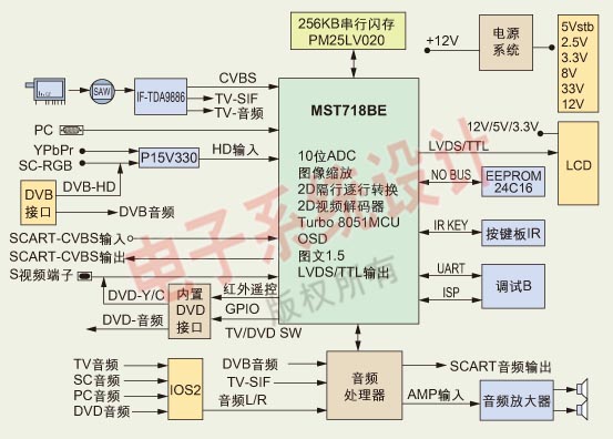
Figure 1: Block diagram of LCD TV platform system based on MST718BE / U (click to enlarge image) 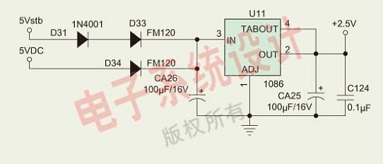
Figure 2: Circuit diagram to provide power for the MST718BE / U chip 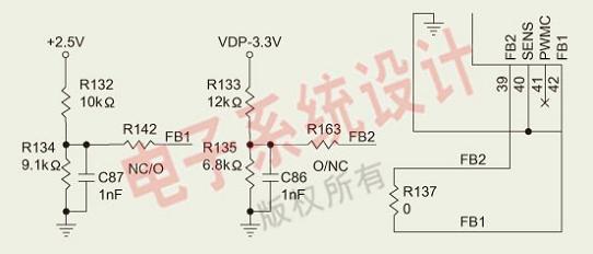
Figure 3: The circuit connection diagram of the external reset pins FB1 and FB2 of MST718BE / U 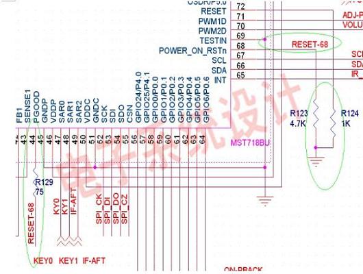
Figure 4: Reset circuit (2) 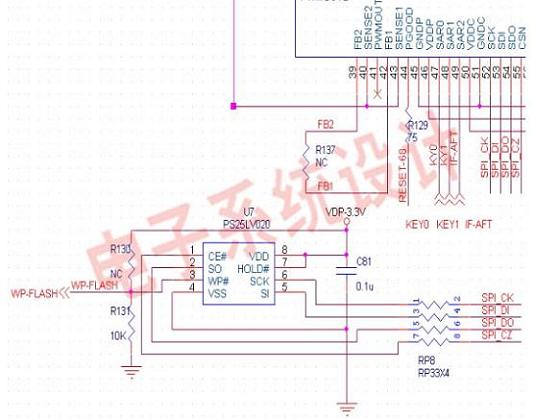
Figure 5: Connection circuit diagram of serial flash memory circuit