Detailed TSN network example
Brand Name: OEM
Product Name: Multi USB Charger
Use: Mobile Phone
Place of Origin: Guangdong, China (Mainland)
Port: 6 port
Input: AC100-240V 50/60HZ
Size: 90*70*16mm
Weight: 250g
Materials: PC+ABS
Color: Black/White
Warranty: 1 year
Multi USB Charger,Multi Usb Wall Charger,Multiple Usb Port Charger,Multi Port USB Charger Shenzhen Waweis Technology Co., Ltd. , https://www.szwaweischarger.com
However, the kit can also work with other vendors' TSN solutions as long as these solutions support the same feature set. Currently, the suite supports 802.1Qbv (planned traffic) and 802.1AS (clock synchronization).
The kit provides 3 Ethernet ports, see Figure 1. It supports almost all standard Ethernet devices, including devices running EtherNet/IP, PROFINET RT, ModbusTCP, BACnet IP or any other IP protocol (except PROFINET IRT, EtherCAT, SERCOS and POWERLINK).
This application note is intended to guide users of the Analog Devices TSN Evaluation Kit (herein referred to as the “TSN Kitâ€) to the steps required to configure and operate the TSN network.
This application note does not replace the TSN suite documentation and users still need to read it. This application note must be used with the TSN Evaluation Kit Quick Start Guide and the fido5100/fido5200 Real-Time Ethernet Multi-Protocol (REM) Switch Data Sheet. 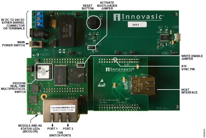
Eval Board Port <br> The PC must be connected to a TSN Ethernet port for configuration. There are 3 ports, one of which is the host port, located on the narrow side of the printed circuit board (PCB) and must be connected to an existing Ethernet device. The device's standard Ethernet traffic is forwarded to the switch TSN port (located on the wider side of the PCB). This forwarding must work before configuring any TSN feature.
The configuration site cannot be accessed through the host port. The default IP address of the TSN suite is 192.168.1.1.
Power Supply <br> Use the power supplied with the kit to power the device, or use screw terminals for power. The board design supports 9 V to 24 V DC voltage.
If screw terminals are used, be sure to follow the markings on the PCB. Note that the PCB is not powered on at the time of delivery.
Configure TSN Suite <br> The following example configures four TSN packages as a linear topology. Therefore, all TSN suites are configured with unique media access control (MAC) addresses and unique IP addresses. These addresses are selected through the Gateway Settings menu, which is located on the TSN Evaluation Kit web page. To enable MAC address writes, the write enable jumper must first be short-circuited. Only one TSN suite can be set at a time.
Note that when setting the MAC and IP addresses, the best practice is to use the lowest three bits of the device serial number as the lowest three bits of the corresponding address because the serial number is always printed on the dual RJ45 connector of the TSN port (RJ45 position See Figure 1, the lowest three digits are 109). If there is an address conflict (which is rare), use more bits in the device serial number. This helps to remember the IP addresses of multiple boards.
If you use a linear topology, it is best to place the board in ascending or descending order (as determined by the user) based on the IP address. This helps to remember the changes made to the board. On the PC used to configure the kit, open a separate tab for each board in the browser and associate the tabs with the kit in the order in which they actually appear. 
To display webcam live video, the PC used to configure the demo can also be used to display live video. This allows you to adjust the TSN suite settings through the web server while displaying the webcam video.
Host Ports <br> An important step in setting up a TSN network using the TSN suite is to let the gateway know the MAC address of the device connected to the host port. Assigning this address to the host port allows the dual port TSN switch to identify the packet that points to that port, and more specifically to the device that is connected to the port. Technically, this MAC address is added to the switch static forwarding database.
To complete the task of setting the host MAC, you must know the MAC address of the device connected to the host port. On automation devices (eg PROFINET devices), MAC is printed on the device housing.
Once found, the host MAC address needs to be entered in the client MAC field on the Gateway Settings page of the Web server.
In Windows systems, physical addresses can be retrieved via the network adapter status. Click the Details button in the General tab of the Local Area Connection Status dialog box.
Use Wireshark and TAP
If the MAC is not available, the easiest way may be to use Wireshark and other tools to observe the incoming and outgoing data packets. The MAC address of the incoming packet of the device is in the destination MAC address field of the Ethernet frame (as long as multicast or broadcast messages are not used), the MAC address of the packet leaving the device is encapsulated in the source MAC address field of the Ethernet frame.
Using Wireshark is important for debugging setup. Before setting up the TSN evaluation kit, it is strongly recommended that you install and become familiar with Wireshark.
However, the use of Wireshark does not mean that all traffic can be seen because the packets in the Ethernet network are not influx; on the contrary, each switch has a forwarding database to determine which port the packet should go through. The route to its destination is the shortest. Therefore, it is recommended to obtain an Ethernet line test access point (TAP).
The TAP is a passive Ethernet component that does not send traffic itself and does not cause delays, but allows people to listen to all packets flowing in either direction. Many vendors offer TAP, and a quick search for "Ethernet TAP" or "Ethernet Test Access Point" over the Internet will return many results, including making your own. This example uses the KUNBUS TAP2100 because it can listen on both connections simultaneously and has a built-in high resolution time base (8 ns).
The ability to listen to both channels at the same time is beneficial for debugging, and can be heard before and after the switch to determine if the switch is filtering out messages or whether the messages are correctly translated into the TSN stream.
Complete basic setup and run <br> All boards and devices for demonstration are set up as shown in the example. After the connection is completed, all TSN packages can be accessed using a web browser. According to the configuration shown in Figure 2, all host MAC addresses Both are added to the gateway settings and the basic settings are completed. With the exception of TSN, this setting should behave like any other Ethernet Layer 2 segment.
The advantage of TSN is that it extends standard Ethernet. The switch speaks at layer 2, instead of layer 3, allowing different IP subnet addresses to avoid address conflicts.
All required communication relationships can still be set without the involvement of the TSN:
ï‚Ÿ Create a project to connect S7-1511 and ET200S. The IP subnet is 192.168.0.xxx.
连接 Use the IP subnet 192.168.10.xxx to connect the IO link demonstration.
设置 Use the IP subnet 192.168.21.xxx to set up and connect the webcam. 
After setting, 802.1AS time synchronization can be run. One of the boards assumes the role of a grandmaster clock. The sign is that its 802.1AS status LED turns red. On synchronous slave devices, the 802.1 status LED turns green when clock synchronization is established.
Check the status of the AS on the TSN evaluation kit web page. It must be understood that the AS is a peer clock. A grandmaster is a master for both TSN ports, but other suites are slaves to the master and hosts to nodes farther away from the master. The port role box reports whether the port is in slave or host mode. If the gateway is not a grandmaster, one port reports that it is in slave mode and the other port reports that it is in master mode. If the gateway is a grandmaster on a TSN network, both ports report that they are in host mode. For more information, see the TSN Evaluation Kit Quick Start Guide. The equivalent scheme is shown in Figure 7.
Note that after the plan is created and enabled, the 802.1AS service requires that queue 3 be opened at some point in the TAS cycle.
Specifying the Grandmaster Function <br> At startup, the device selects a clock master using the best host clock algorithm (BMCA). In most cases, this is sufficient and no further attention is required. However, in some cases it may be better to use a fixed machine.
Using the "Local Host Priority 1:" and "Local Host Priority 2::" entries on the Time Synchronization page, you can direct the best host algorithm to select a specific board as the genlock clock. Figure 8 shows an adjusted TSN kit. Priority 1 is set to 200 (priority is higher than the default of 248; therefore, the board assumes the master clock role).
Set up TSN flow
The TSN flow ID consists of locally assigned multicast addresses and 802.1Q VLAN tags. This example setup uses the following streams, as listed in Table 1. 

Use the VLAN tagged destination MAC address and priority code point (PCP) for PROFINET, which allows high-priority data traffic to be allocated to the TSN stream. PROFINET uses VLAN PCP 6 to tag all prioritized traffic.
Creating and Setting Up an 802.1Qbv Schedule <br> After you have set up your hardware and communications settings and synchronized the 802.1AS clock, you can create a plan. But before that, it is recommended that you review the Ethernet basics first.
Review: Ethernet Frames and TSN
From a software perspective, Ethernet frames consist of Layer 2 header information (target and source addresses, EtherType), up to 1500 bytes of data (assuming no jumbo frames are used), and CRC32. When the computer receives an Ethernet frame, the Ethernet header and data fields in the frame are copied to the computer's main memory.
In addition, the Ethernet frame on the line contains a 63-bit preamble, a 1-bit start delimiter, and a minimum 12-byte line silence interval. The minimum length of an Ethernet frame is 64 bytes (including CRC). The relatively long preamble and silence times, as well as the minimum length, originate from older Ethernet versions but still need to be maintained and guaranteed. However, some PHYs allow the preamble to be shortened to 16 bits, but this is not a common practice.
The TSN stream adds 4 bytes to the standard Ethernet frame, the VLAN tag. This stream always contains a VLAN tag. The VLAN tag consists of a priority (PCP) and a VLAN ID. The VLAN ID forms the TSN flow identifier together with the target MAC. There can only be one sender (talker) per TSN stream, but there can be one or more receivers (listeners). In any frame length calculation, these four bytes must be added (see Table 3). The minimum time (100 Mbps) that the frame occupies on the line is 6.72 μs, and the entire 1500-byte frame takes 123.36 μs.
Ethernet transmission channel timing model <br> Although Ethernet is quite fast, the delay of the transmission channel needs to be considered. For a 100 Mbps full-duplex Ethernet environment, consider the following parameters:
PHY PHY latencies: Ethernet PHYs introduce delays during data reception and transmission due to internal processing. The receive (RX) delay is usually greater than the transmit (TX) delay. In addition, RX timing may cause jitters of around a few nanoseconds. These delays are in the order of hundreds of nanoseconds and are related to the PHY element. One byte occupies 80 ns, so the PHY delay is 1 to 4 bytes delayed.
桥 Bridge Delay: Ethernet switches introduce bridge delays (delay times for messages passing through the switch). For a straight-through dual-port switch, the bridge delay is small. Before making a forwarding decision, the switch must receive an 8-byte preamble, a 12-byte source/destination MAC address, and a 4-byte VLAN tag. The sum of these requirements is a minimum bridge delay of 1.92 μs (note that there are other factors that may cause a slight increase in bridge delay).
电缆 Cable delay: The typical CAT5 cable has a delay of 5.7 ns per meter, or approximately half of the transmitted bits. For desktop setups or cabinets with short cables, the cable delay is approximately one order of magnitude lower than the PHY delay. However, for a full-length 100 m Ethernet cable, the cable delay will increase by 570 ns (approximately 7 bytes).
For a system with a wide physical range (long cable length) and/or many nodes, to calculate a complex plan for it, all these delays must be considered. For this desktop demonstration, a 10,000 ns margin should be added to the plan to make the results reliable.
802.1Qbv scheduler operation
The IEEE defines up to eight queues for Qbv, also known as a time-aware shaper (TAS). The IEEE also defines a set of bytes, one byte for a certain offset in the period. Each bit in these bytes enables or disables the corresponding queue. With each slice in a cycle, one byte defines which queues are enabled and which are disabled. In the enabled queue, the queue with higher priority is processed. It must be known that the time slices in the cycle can have any starting offset, and these offsets are in nanoseconds (ns). The unit of cycle time is also nanoseconds (ns).
When idle, the Ethernet transmitter acquires an Ethernet frame from the queue with the highest priority among all enabled queues. When the sender is busy sending the frame, it does not acquire other frames (meaning there is no other send queue).
The TAS currently implemented by the TSN suite is limited to 4 queues, with a maximum of 16 offsets (also called gate open events) in a cycle.
The following figure shows the TAS scheduler block diagram. In this figure, all queues have some Ethernet frames queued and define four offsets: 0 ns, 500 ns, 1000 ns, and 2000 ns. In this example, the cycle time is 2500 ns. Figure 14 shows a 2000 ns valid offset, causing queue 2 and queue 3 to be blocked and queue 0 and queue 1 enabled. Queue 1 has a higher priority than queue 0, so the sender gets the next frame from queue 1 until queue 1 is empty or the current time slice runs out. If the current time slice runs out, the next time slot offset 0 will enable queue 0, but since queue 3 has messages queued and higher priority, the next frame to be sent is selected from queue 3.
When all queues are enabled at the same time, TAS works like a classic Quality of Service (QoS) priority queue and serves the highest priority queue first. 
Guard band <br> When using the scheduler to guard the bandwidth, it must be ensured that the transmitter is idle when the higher priority gate is opened. If the sender is not idle, a lower priority long frame may prevent or at least delay higher priority traffic. In order to ensure that the transmitter is idle and can immediately start sending higher priority traffic, a guard band should be inserted. When the guard band is active, it disables the sender from acquiring the next frame.
To achieve this goal, the guard band must be long enough so that the longest message that may be queued in a particular queue is completed successfully before the next gate open event occurs. The size of the longest message that may be queued is defined in the "maxSDU" parameter, in bytes.
Instead of disabling all queues to create the guard bands manually, the TSN Suite automatically handles guard band related transactions.
The following figure shows a simple example. At t0, the scheduler is enabled for the first time. Before this time, ie to the left of t0, all gates open. During the send gate enable time, the transmitter can acquire frames from queue 0 (Q0 in this case, one gate at a time). The guard band time (see Figure 15) is the guard band before the queue 3 opening event, which is wide enough to allow a complete 1522 SDU frame to be safely sent and then a Q3 gate open event.
When Q3 is turned on, both periods are much shorter because Q3 is only used to transmit shorter frames. Its maxSDU may only have 200 bytes.
The maxSDU of queue 0 is a fixed value of 1522. Web traffic of the web server is allowed to pass through queue 0 without packet loss. 
For PROFINET RT, a stream can be defined specifically for periodic data, with few additional frames in the stream, or even not. Therefore, the estimation of maxSDU will be more accurate. However, the TSN suite is not synchronized with PROFINET RT (PROFINET RT protocol does not have this capability), and PROFINET periodic communication runs on its own clock. To ensure that each frame is sent within the PROFINET cycle time, the TAS cycle time must be less than (faster than) PROFINET; the best practice is twice as fast.
Creating an effective and compact schedule is not easy for the following reasons:
帧 Frame size may vary. The scheduling must consider the worst case, not the most frequent one.
• The frame rate may be different because of the extra frames (handshaking, rare commands, etc.) to send.
• The application cycle is out of sync with the TAS cycle (oversampling required).
• Flows with different cycle times need to co-exist on one line. One way to solve this type of problem is to use a slower TSN plan and open the gate multiple times for faster traffic during the TSN cycle.
It is possible to synchronize the application with the TAS scheduler. The TAS sync pulse (when one cycle is started or completed) is provided by pin A10 of the CPU module on the TSN kit. The application can use this signal to synchronize with the TAS cycle so that oversampling is not required.
Finally, you must consider the TSN kit block diagram (see the figure below). Each Ethernet port corresponds to a TAS scheduler. If a frame is received through an Ethernet port, the TSN suite checks for a known TSN flow ID. If a TSN flow is identified, reverse flow conversion is applied and the frame is sent to the host port. If it is not identified, or it is a "best-effort" traffic with no matching IP address, the frame will be placed in the "other port" TAS queue for transmission.
PROFINET IRT uses planned traffic even before TSN is available. This simplified forwarding is called "relative repeater." Only the traffic that is not forwarded is recognized and the transmission time of the forwarded frame is relative to the receiving time (bridge delay). This contrasts with absolute transponders in PROFINET terminology.
The absolute transponder first looks for the target port and then sends the frame at an absolute time (planned). This absolute time must consider the bridge delay and lookup time. Therefore, absolute transponders are slightly slower and more complex than the relative transponders. One application of an absolute transponder is a multi-port switch where the lookup of the egress port will happen anyway.
If a frame is received through the host port, it is checked against the defined stream conversion filter. If it is not converted, the traffic will be queued in TAS's "best-effort" queue. The appropriate port is selected through the switch's dynamic forwarding database, but if a flow transition occurs, the port through which the frame leaves can be specified. Therefore, the flow transition configuration page allows selection of port 1, port 2, or both ports as desired exit ports. 
(Author: ADI company Volker E. Goller)