Classification and formal analysis of circuit grounding
1. The grounding classification grounding can be divided into two categories according to its function: 1 protection personnel and equipment are not damaged and called protection grounding; 2 the normal operation of the equipment is called working grounding. The classification here refers to the various requirements considered in the design and construction of the grounding engineering, and does not mean that each "ground" needs to be independent. On the contrary, in addition to special reasons such as anti-interference of geoelectric signals and special requirements of the equipment itself, it is recommended to adopt a joint grounding scheme as much as possible. Lightning protection grounding is a grounding system to prevent damage when subjected to lightning strikes (direct strikes, induction, or line introduction). There are often signal (weak) lightning protection grounds and power supply (strong power) lightning protection grounds, the reason for the distinction is not only because of the required grounding resistance, but also in the engineering practice, the signal lightning protection is often attached to the signal independent ground, and The power supply is built separately from lightning protection. The safe grounding of the casing is to form a good conductive connection between the metal parts of the system (the cabinet casing, the console casing, etc.) and the ground to protect the equipment and personal safety. The reason is that the power supply of the system is a strong power supply (380, 220 or 110V). Under normal circumstances, the chassis is not charged. When a fault occurs (such as a host power failure or other fault), the power supply of the power supply and the conductive metal of the casing are caused. When the components are short-circuited, these metal parts or casings form a charged body. If there is no good grounding, there is a high potential difference between the charged body and the ground. If people accidentally touch these charged bodies, then It creates danger through the formation of a pathway through the body. Therefore, it is necessary to make a good connection between the metal casing and the ground so that the casing and the ground are equipotential. In addition, the protective grounding also prevents the accumulation of static electricity. The working ground is the grounding for the system and the instruments connected to it to operate reliably and to ensure measurement and control accuracy. The signal ground (SG) is the sensor and source zero potential of various physical quantities and the common reference ground (relative zero potential) of the signals in the circuit. Here, the signal generally refers to an analog signal or a weak digital signal, which is susceptible to fluctuations in power supply or external factors, resulting in a decrease in the signal-to-noise ratio (SNR) of the signal. Especially the analog signal, the drift of the signal ground, will lead to a decrease in the signal-to-noise ratio; the measured value of the signal will produce errors or errors, which may lead to system design failure. Therefore, the requirements for the signal ground are high, and special processing is needed in the system to avoid direct connection with high-power power ground, digital ground, and easily generated interference ground. Especially for the measurement of small signals, the signal ground usually needs to be isolated. 1.2.2 Analog Ground (AG) is the common reference ground for the zero potential of analog circuits in the system. Because the analog circuit not only handles the processing of small signals, but also the power processing of large signals; there are both low-frequency processing and high-frequency processing; the analog quantity is very different from energy, frequency, time, etc., so the analog circuit is easy. Interference is accepted and interference may occur. Therefore, the grounding point selection of the analog ground and the laying of the grounding wire should be fully considered. Reduce the wire resistance of the ground wire, open the analog and digital parts of the circuit, and finally connect them together by inductive filtering and isolation. Digital ground (DG) is the common reference ground for the zero potential of digital circuits in the system. Since the digital circuit operates in a pulse state, especially when the front and rear edges of the pulse are steep or the frequency is high, a large burr is generated in the power supply system, which is likely to cause interference to the analog circuit. Therefore, the grounding point selection of the digital ground and the laying of the grounding wire should also be fully considered. Try to separate the analog and digital parts of the circuit, and finally connect them together through the inductor. 1.2.4 Suspended ground The floating ground (FG) is the ground of part of the circuit in the system not directly connected to the ground of the whole system, but is connected by transformer or directly connected, and is in a suspended state. The level of this part of the circuit is the potential relative to its own "ground". It is commonly used in small signal extraction systems or in hybrid systems with strong and weak points. The advantage is that the circuit is not affected by electrical and interference in the system; the disadvantage is that the circuit is susceptible to parasitic capacitance, causing the ground potential of the circuit to fluctuate and increasing the induced interference to the analog circuit. Since the ground of the circuit is not connected to the system ground, it is easy to generate static electricity and cause electrostatic discharge, which may cause electrostatic breakdown or strong interference. Therefore, the effect of the floating ground depends not only on the magnitude of the insulation resistance of the suspension, but also on the magnitude of the parasitic capacitance in suspension and the frequency of the signal. In the VDD-SGND power supply system shown in the figure below, all operating points are grounded at SGND, but the level is floating between SGND and DGND. The system of VDD-SGND is connected to the whole system. It is completely coupled by a transformer, and it is necessary to pay attention to the connection method of the signal when designing here. The power ground is the common reference ground for the system power supply zero potential. Since the power supply is often supplied to each unit in the system at the same time, and the power supply characteristics and parameters required by each unit may be greatly different, it is necessary to ensure stable and reliable operation of the power supply, and to ensure that other units work stably and reliably. 1.2.6 Power ground The power ground is the common reference ground of the zero potential of the load circuit or power drive circuit. Since the current of the load circuit or the power drive circuit is strong and the voltage is high, the interference on the power ground is large. Therefore, the power ground must be separately and separately wired with other weak current grounds to ensure stable and reliable operation of the entire system. 2, the form of grounding In the low-frequency circuit, the operating frequency of the signal is less than 1MHz, and the influence of the inductance between the wiring and the device is small, and the circulating current formed by the grounding circuit has a great influence on the interference, so a grounding should be adopted. When the signal operating frequency is greater than 10MHz, the ground line impedance becomes very large. At this time, the ground line impedance should be reduced as much as possible. When the operating frequency is between 1MHz and 10MHz, if a grounding is used, the grounding length should not exceed 1-20 of the wavelength. Otherwise, the multi-point grounding method should be adopted. The working grounding adopts several grounding methods as shown in the figure according to the working frequency. Low-frequency (<1MHz) single-point grounding (that is, a structural point in the entire circuit system is considered as a ground reference point, all ground connections are connected to this point, and a safety grounding bolt is set) Preventing two-point grounding produces a circuit-coupled coupling of common ground impedance. The single-point grounding method of multiple circuits is divided into two types: series and parallel. Since series grounding produces a circuit-coupled coupling of common ground impedance, the low-frequency circuit is preferably a single-point grounding type in parallel. Circuits with operating frequencies between 1 MHz and 10 MHz are hybrid grounded. When the length of the grounding wire is less than 1/20 of the wavelength of the working signal, the single-point grounding type is adopted, otherwise the multi-point grounding type is adopted. Make reasonable arrangements according to the needs of the system and the needs of the circuit. 2.4 Suspension grounding The suspension grounding is that the ground of the system is not directly connected to the earth, but is connected by a transformer or directly connected, and is in a suspended state. Suspended grounding should pay attention to the following points: (1) Try to improve the grounding insulation resistance of the floating system, which is beneficial to reduce the common mode interference current entering the floating system and ensure the reliability of the system. (2) Pay attention to the large parasitic capacitance of the floating system to the ground. The high-frequency interference signal may still be coupled to the floating system through the parasitic capacitance. It must be paid attention to during design. (3) Suspension grounding technology must be combined with electromagnetic compatibility technologies such as shielding and isolation to achieve better expected results. (4) When using floating technology, the system easily accumulates static electricity. When the static electricity accumulates to a certain extent, it can cause a lot of damage to people and equipment, so pay attention to the harm of static electricity and voltage counterattack to equipment and human body.
Description of Antenk's Slim D-Sub Connector
D-Sub Connector Slim is a space-saving D-sub Socket Connector with an 8.54mm depth. The slim 8.54mm depth reduces the board mounting area by 33% as compared with standard models. The Slim Profile D-Sub Connectoroffering includes D-sub sockets with nine right-angle DIP terminals and a mounting board thickness of either 1.6 mm or 1.0 mm (from difference in lock pin structure). RoHS compliant, Slim D-Sub Connector offers a 3A rated current, 300VAC rated voltage, and an insertion durability of 100 times within an operating temperature range of -25º to 105ºC.
Features of Antenk's Slim D-Sub Connector
Board mounting area is reduced by 33% (compared with standard models) using a depth of 8.4mm
D-sub sockets with nine right-angle DIP terminals
Mounting board thickness of either 1.6mm or 1.0mm (from difference in lock pin structure)
RoHS Compliant
Applications of Antenk's Slim D-Sub Connector
Factory Automation
Machine Tools
Power SuppliesMedical Tools
Test & Measurement
LSI/FPD Manufacturing Systems
Information Transmission Tools
Security Tools
Industrial Tools
Slim D SUB Connector,High Density D-Sub Connector Slim, Solder type D-Sub Connector Slim,Right Angle D SUB Connector Slim, slim profile 90°- SMT D SUB Connector,9 15 25pin slim profile 90°- THT D SUB Connector ShenZhen Antenk Electronics Co,Ltd , https://www.pcbsocket.com
1.1, protective grounding
1.1.1 Lightning protection grounding
1.1.2 Chassis safety grounding
1.2, working ground
1.2.1 Signal ground 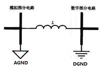
1.2.3 Digitally 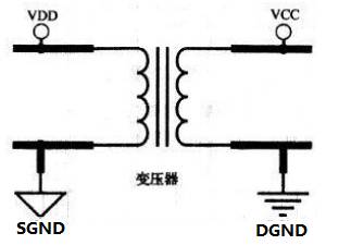
1.2.5 Power Ground 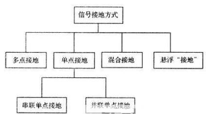
2.1 Single point grounding 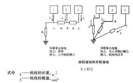
In order to prevent power frequency and other stray currents from causing interference on the signal ground, the signal ground should be insulated from the power ground and the chassis ground, and only in the power ground, the chassis ground and the ground wire connected to the ground. Connect the safety grounding bolts (except floating type). In order to prevent power frequency and other stray currents from causing interference on the signal ground, the signal ground should be insulated from the power ground and the chassis ground, and only in the power ground, the chassis ground and the ground wire connected to the ground. Connect the safety grounding bolts (except floating type). 2.2 Multi-point grounding The high operating frequency (>10MHz) adopts multi-point grounding. In this circuit system, a ground plane is used to replace the respective ground loop of each part of the circuit. Since the inductive reactance of the ground lead is proportional to the frequency and length, when the operating frequency is high, the common ground impedance is increased, thereby increasing the electromagnetic interference generated by the common ground impedance, so the length of the ground line is required to be as short as possible. When using multi-point grounding, try to find the closest low-resistance ground plane to ground. Here, the circuit board is preferably designed as a multilayer circuit (more than 4 layers), providing a layer as a ground plane. 2.3 Hybrid Grounding