Analysis on the realization of wireless LED lighting drive system
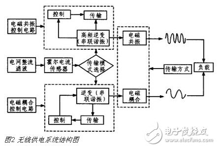
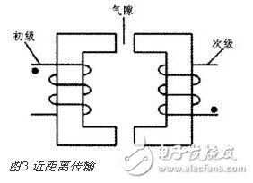
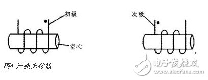
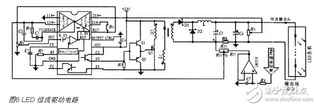
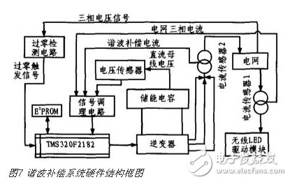
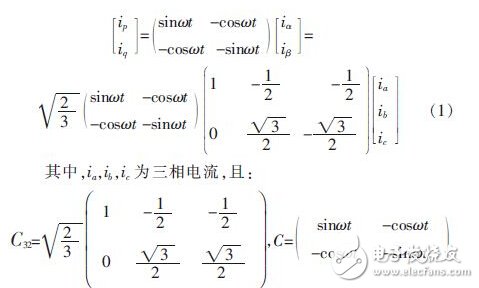
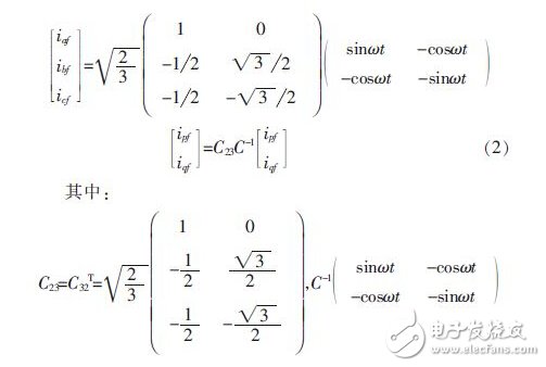
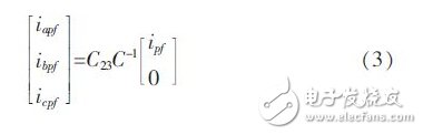
LED light sources have developed to a new level in the past decade, and are soon applied to the terminal markets such as automobiles, buildings, medical, landscape Lighting, etc. LED lighting has become more reliable and efficient than traditional lighting, and is increasingly becoming more popular in the market. popular. However, the installation and use of LEDs are constrained by the laying of power lines, which affects the flexibility of their use. At the same time, due to the presence of LEDs, high-frequency transformers such as drive sources, power switch tubes, etc., it will lead to the introduction of the grid. The harmonic current increases, which affects the power quality of the grid. At present, it is rare to have a complete set of system reports that consider reducing the harmonic effects of wireless power supply to the grid. Therefore, this paper presents a set of LED wireless drive solutions with harmonic compensation. This solution can adjust the LED to the appropriate brightness according to the illumination feedback feedback while facilitating the flexible installation of the LED. These popularizations of LEDs, improving power supply safety and reliability, and saving energy efficiently will be very beneficial. 1 overall design of the system The system mainly includes: wireless power supply module, constant current drive source module, active power filter (APF) module, control circuit, and the overall block diagram of the system is shown in Figure 1. Among them, the inverter device and the rectification filter 2 constitute a wireless power supply module; the forward conversion circuit and the rectification filter 3 constitute a constant current source drive module. The MCU performs light feedback on the photocell to feedback-regulate the output current to stabilize the output and constant current. The APF outputs current through the main controller to offset the current harmonics injected into the grid by the wireless drive module to improve the power quality at the input. 2 system circuit design 2.1 Wireless power supply system design The wireless power supply system consists of a control terminal, a transmitting end, and a load rectification circuit. The electromagnetic power supply is realized by electromagnetic coupling (near-distance transmission mode) and electromagnetic resonance (long-distance transmission mode), and the system structure diagram is shown in FIG. 2 . The transmitting end is mainly composed of an inverter and a transmission channel. The inverter is responsible for converting direct current (DC) into alternating current (AC), which consists of an inverter bridge, control logic and filter circuits. The short-range inverter frequency is 200~500 kHz, which is transmitted by electromagnetic coupling. The U-shaped loosely coupled ferrite core is isolated to achieve wireless power supply, as shown in Figure 3. The long-distance inverter frequency is 1 MHz. It is transmitted by electromagnetic resonance. It is coupled by an air-core transformer. The primary and secondary are wound on the cylinder respectively to serve as a transmission medium to achieve long-distance power transmission, as shown in Figure 4. The system achieves stable and efficient transmission of electric energy through intelligent switching transmission mode. The relationship between the primary equivalent resistance and the distance is shown in Figure 5. z is the impedance and L is the distance. Only the equivalent impedance at the position of L0 is the smallest. According to this principle, when the receiving distance is far from L0, the impedance increases, the primary current decreases, and the primary input current is collected by the Hall current sensor to judge the mode switching. 2.2 constant current source circuit The constant current source system is mainly composed of a DC/DC forward conversion circuit and an MCU control circuit. The forward conversion circuit is an LED constant current driving source, as shown in Figure 6. The inverter output is rectified and filtered, and is regulated by the chip L7824ACV to provide +24 V input for the DC/DC converter circuit. The constant current source of the structure has the characteristics of high-precision output, and its output power depends on the selection of the transformer parameters, and generally can reach more than 32 W, which satisfies the power requirements of most people's LED lighting applications. The circuit uses TL494 as the constant current control chip. The switching frequency fosc is set by the formula fosc=1.1/(RTCT), and the dead time is adjusted by the potentiometer R4. The current output error can be “1%. In Figure 6, RS is the current sampling resistor; R3 is the feedback voltage sampling resistor to limit the maximum output voltage. When the output current changes, the potential of pin 2 (1IN-) also changes. After the internal error amplification of TL494 is compared, the duty cycle of the PWM drive signal is changed to achieve negative feedback adjustment of the output current. The MCU collects the photocell voltage through A/D. After the judgment, the output PWM is converted into a reference voltage whose size is proportional to the duty ratio through the low-pass filter to change the output current to achieve the purpose of automatically adjusting the LED luminous intensity. The voltage follower acts to isolate and enhance the drive capability. Adjusting R2 changes the proportional relationship between the reference voltage and the output current. L1 and D3 are magnetic bleeder windings to prevent magnetic saturation of the primary winding of the transformer, enabling magnetic reset of the primary coil during switching off. Due to the limited drive capability of the TL494, the TL494 drive capability is increased by the push-pull output of the triode. Table 1 shows the physical test results of the DC/DC converter circuit with the output of 16 W as an example. It proves that the constant current source can achieve higher efficiency and high precision current output. 2.3 Harmonic Compensation System 2.3.1 System Hardware Structure The hardware of the harmonic compensation system is mainly completed by the active power filter (APF), and the structure is shown in Figure 7. This article uses the TMS320F2812 digital signal processor (DSP) as the core control and signal processing unit. The conditioning circuit mainly includes current/voltage sensor signal amplification, rectification, and anti-aliasing filtering. The current sensor 1 samples the three-phase current of the load terminal, and sends it to the DSP through the signal conditioning circuit for A/D acquisition, and then performs harmonic current extraction algorithm and control algorithm processing, and drives the inverter to cancel the harmonic current correspondingly, with current The compensation current of the sensor 2 sampling output is used for feedback adjustment. The DC bus voltage of the inverter is converted to the internal A/D acquisition of the DSP by the Hall voltage sensor, and the DC side capacitor voltage is controlled by an algorithm. The zero-crossing point of the three-phase voltage signal acts as a zero-crossing trigger signal, and the software clears and starts the signal as each cycle. 2.3.2 Harmonic current extraction algorithm 1) Three-phase instantaneous reactive power principle The software part of the compensation system mainly includes the harmonic current extraction algorithm, which adopts the commonly used three-phase instantaneous reactive power theory (also known as ip-iq algorithm). The detection method organically combines the three-phase current with the ip and iq current components decomposed based on the theory by a transfer matrix, and as a starting point, three-phase current harmonics and reactive currents can be respectively obtained, and the expression thereof is obtained. The formula is: The component of the corresponding fundamental current can be separated by a low-pass filter (LPF). Since ipf, iqf can be obtained by transforming the fundamental component iaf, ibf, icf, ipf, iqf can obtain three-phase current through inverse transformation. In the iaf, ibf, icf is: When it is required to detect both harmonics and reactive currents, it is only necessary to ignore the channel for calculating ip. The fundamental active components of the detected current are calculated by ipf, ibpf, icpf, ie: Subtracting ia, ib, ic from iapf, ibpf, and icpf yields the harmonic component wave and the fundamental reactive component of ia, ib, ic. 2) Simulation results The algorithm is simulated based on the simulation mode of DSP compilation environment CCS3.3. It is assumed that the original three-phase input current is a 50 Hz sine wave with a phase difference of 120°, and the single-phase clipped distortion is taken as an example. Figure 8(a) shows the single-phase clipping distortion waveform, calculated according to the total harmonic distortion rate (THD): 3 Conclusion The system has no wires limitation, LEDs can be arbitrarily installed within the wireless power supply acceptance range, and the LED brightness is adjusted by the photoelectric sensor's automatic sensitization. At the same time, using the active power filter harmonic compensation technology, the harmonic elimination device matched with the wireless drive module is designed to filter out the high-order current harmonics in the system operation and reduce the total harmonic distortion of the transmission network. The design can be applied to home, car, scene or landscape LED lighting, effectively improving the flexibility of lighting distribution, saving power and reducing light pollution, and improving power quality, and has broad application prospects. Zhejiang Baishili Battery Technology Service Co,.Ltd. , https://www.bslbatteryservice.com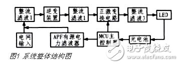


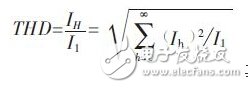 Ih is the effective value of each harmonic current, and I1 is the effective value of the fundamental current. The spectrum analysis of the waveform can calculate the initial current of the phase as 12.2%. Figure 8(b) shows the fundamental waveform after the harmonics are extracted by the algorithm. After filtering by the three-phase instantaneous reactive power algorithm, the harmonic current is basically eliminated and the original waveform is restored.