High-power, low-cost, two-stage solution for regulating constant voltage in LED drivers
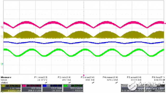
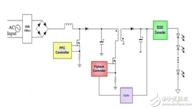
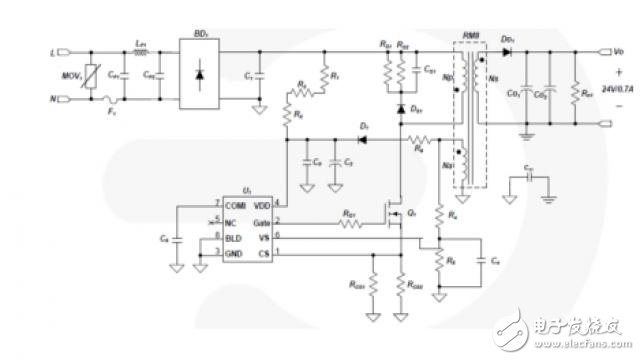
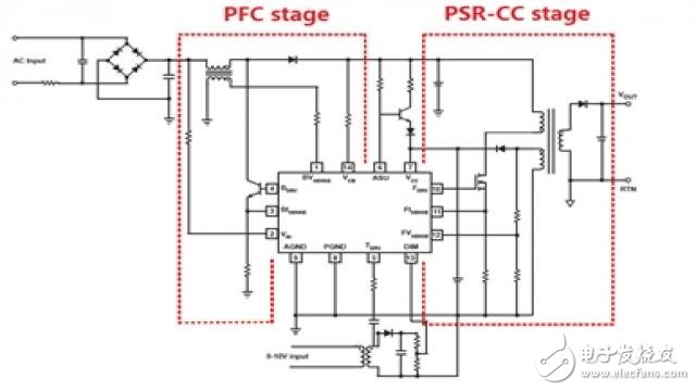
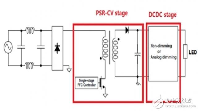
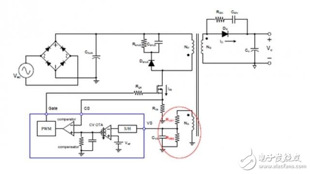
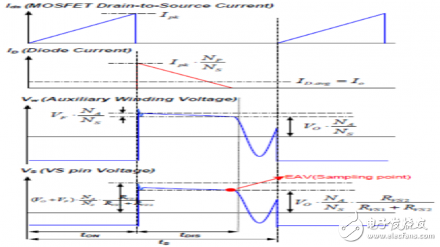
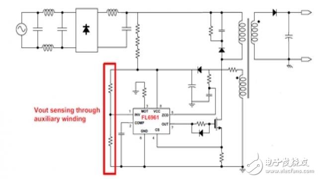
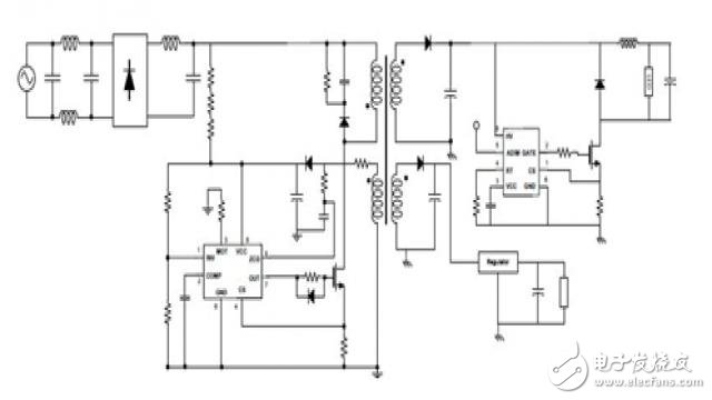
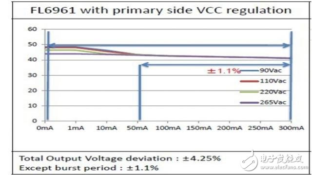
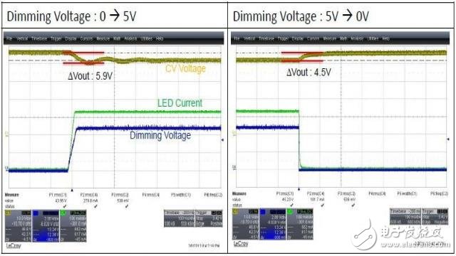
At present, there is an increasingly popular trend in the field of LED lighting, that is, while ensuring a high power factor, the wireless channel frequency has a low ripple current. The Japanese market requires that the clamp current ripple ratio be less than "1.3" and the ripple frequency should be higher than 100 Hz; ENERGY STAR has similar requirements, and the output operating frequency must be ≥ 120 Hz [1]. Figure 1: Energy Star Requirements for Integrated LED Lights CH3: VLED, CH4: ILED Figure 2: Line frequency ripple current in a 17W single stage In order to have a high power factor, the single-stage PFC PSR-CC does not have a step-down E-cap, so the line frequency ripple current cannot be eliminated. In some high-end lighting applications, single-stage PSR-CC cannot be used. The traditional solution uses three levels: the PFC stage, the flyback converter stage, and the secondary DCDC stage to solve this problem, as shown in Figure 3. Figure 3: Three-level solution Obviously, although the circuit performs well, it is too complicated, contains too many components, and the cost is not low enough to take up too much space. The two-stage solution in this article uses PSR technology to save on first-class costs while maintaining high performance (wireless channel frequency ripple current and high power factor). Part 1 lists the circuit performance analysis of the PSR-CC and PSR-CV solutions; Part 2 explains how to implement the two-stage PSR-CV solution. Part 3 explains the experimental results of the prototype of the two-stage PST-CV solution; the last part summarizes the conclusions of the study. From the perspective of PSR technology depending on the control objectives, there are two control methods in total: constant voltage regulation and constant current regulation. Because the LED current determines the light intensity, so single stage PFC PSR-CC is often used in lighting applications. Figure 4: Typical single-stage PSR-CC solution In order to eliminate the line frequency ripple current and meet strict standards, we must use a multi-level solution. PSR technology does not require a secondary feedback loop and optocoupler, and its regulation is very strict, enabling a two-stage solution. Based on a three-level solution, we can implement a bipolar solution using PSR technology in two different ways: The first two-stage PSR solution combines a flyback converter stage with a secondary DCDC stage to achieve isolation and drive, LED dimming, and a PFC stage. As shown in Figure 4, the LED current is controlled at the primary side, so the solution is also known as the two-stage PSR-CC. Figure 4: Two-stage PSR-CC solution The two-stage PSR-CC solution market responded well, especially in the tangential dimming field – dimming signals came from AC lines. But in analog or PWM dimming, the situation is completely different. Since the dimming function is done on the primary side, this solution requires a transformer to isolate the dimming signal from a safety perspective. Due to the primary dimming, the dimming control is more complicated and difficult to implement. In addition, relatively weak CC regulation due to PSR-CC is a weakness in high-end lighting applications. The dimming range is another issue that needs to be considered in this topology. Based on a single-stage solution and a two-stage PSR-CC solution, another new two-stage structure for wireless channel frequency current ripple applications is also available. The focus of this architecture is to combine the PFC stage and the flyback conversion stage to the same level to achieve the well-known PFC and isolation functions [2]. Compared with PSR-CC, the main difference is that this single stage only controls the secondary output voltage and does not control the output current, so it is named PSR-CV. On the right is the DCDC stage used to drive or dim the LEDs. As shown in Figure 5, the two-stage PSR CV has a very significant functional level: the PFC function is implemented on the primary side, while the LED driver is implemented on the secondary side, which reduces the difficulty of the circuit and simplifies the circuit design. Figure 5: Two-stage PSR-CV solution The two-stage PSR-CV solution not only maintains the quality of the two-stage PSR-CC, but also has many other advantages. First, LED current control is very simple, and because the secondary DCDC stage directly controls the LED current, the LED current of this solution is also more accurate. Second, for dimming applications, any analog dimming or PWM dimming between 0 and 10V can be easily accomplished without any isolation in the secondary DCDC stage. Third, the cost is lower than the PSR-CC. Compared to PSR-CC, we can think of this structure to move the PFC stage to the secondary DCDC level. It is well known that the PFC stage contains high voltage devices, but the low voltage devices are included in the secondary DCDC stage. Finally, the PSR-CV solution gives users more flexibility. For example, we can add standby power to the PSR-CV stage to achieve low standby power when the LEDs are not connected. Alternatively, we can choose the appropriate DCDC for multiple strings of applications. The only drawback of this solution is that the PSR-CV output voltage regulation is not very strict, but we can overcome this problem by selecting a secondary DCDC with a wide input range. Currently, the PSR-CV is implemented by controlling the voltage on the auxiliary winding. Once the auxiliary winding voltage is controlled, the output voltage can be set by transformer coupling. Therefore, in order to have a precise output voltage, as shown in Figure 6, we need to directly control the voltage at the auxiliary winding end. Figure 6: Simplified accurate PSR-CV control During the conduction of the rectifier diode, the sum of the output voltage and the forward voltage drop of the diode reacts at the auxiliary winding end as (Vo+VF)  Naux / Ns. Since the forward voltage drop of the diode decreases as the current decreases, the auxiliary winding terminal voltage best reflects the output voltage at the end of the diode conduction time, at which point the diode current is reduced to zero. More accurate output voltage information can be obtained by sampling the winding voltage at the end of the diode conduction time. Figure 7: Main waveforms in PSR-CV control Since the voltage drop at the auxiliary winding end fluctuates up and down during a single switching, we need to find the sampling point first, then use the sample/hold circuit, and then compare the induced voltage with the internal precision reference voltage. In short, the control logic is more complicated. Another easy way to achieve this is as shown in Figure 8. We can control the rectified auxiliary winding voltage through the error amplifier of the PFC controller. The disadvantage of this approach is that the output voltage is relatively less accurate. Figure 8: Simple PSR-CV Control However, this is a compromise between simple control and precision output voltage. In the two-stage PSR-CV solution, the output voltage precision of the first stage is not very important. We can overcome this disadvantage by selecting a secondary DCDC with a wide input range. Based on the OVP-enabled single PFC controller FL6961, we have created an evaluation board that can be modified to implement the PSR-CV and the high-voltage buck controller FL7701 [3] with an extremely wide input range. Figure 9: Complete solution for PSR-CV plus DCDC With the PSR-CV solution, we can easily generate a secondary CV supply that powers other accessories such as the MCU by loading the auxiliary windings on the secondary side. With the PSR-CV Vcc adjustment, we can see that the CV accuracy can achieve ±4.25% CV tolerance over the entire output load range. If the drift of the optical load voltage is removed (caused by burst mode), the CV accuracy will increase to ±1.1%. Figure 10: CV Performance With the FL7701, it is easy to build a step-down DCDC with internal analog dimming. The complete solution therefore has a very low ripple current. This paper introduces and develops a new two-stage PSR-CV solution that guarantees the simplicity of the circuit and the ease of design, while the wireless channel frequency current ripple has a high power factor. Experimental results show that the proposed two-stage PSR-CV solution is ideal for high-end LED analog dimming and PWM dimming applications. In the future, we will add new features, such as increasing standby power at the primary side to achieve low standby power consumption to meet the trend of LED drivers. Pure sine ware output
DC Start & Automatic Self-Diagnostic Function
On/Off Grid Solar Inverter,Hybrid Inverter With Mppt Charge,pure sine wave solar inverter suzhou whaylan new energy technology co., ltd , https://www.whaylan.com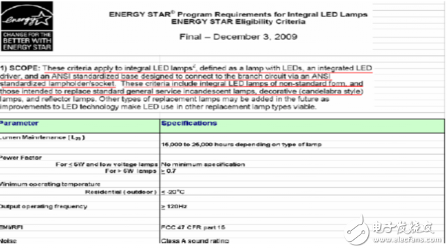
Optional MPPT/PWM solar charge controller 60A
MPPT Efficiency max 98%
