A comprehensive introduction to vehicle tracking systems
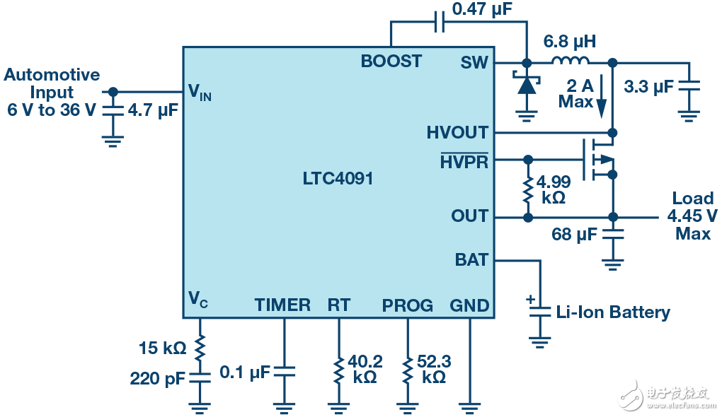
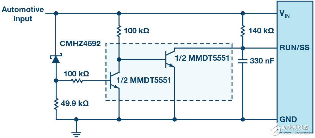
The proportion of vehicles and fleets using vehicle tracking systems is rising. The shape and size of modern trackers have been reduced and their functions have been enhanced to support active data transmission for real-time tracking. In addition, backup capacity and lower voltage are needed to power the system's GPRS chipset. Vehicle tracking systems are ideal for monitoring individual vehicles or entire fleets. The tracking system consists of automatic tracking hardware and data acquisition software (and data transmission if required). The global fleet management market size was USD 8 billion in 2015 and is expected to exceed USD 22 billion by 2022, with a compound annual growth rate of more than 20% from 2016 to 2023 (Source: Global Market Insights). The growing demand for commercial vehicles in Latin America, the Middle East and Africa is also a potential growth opportunity. In developed regions such as Europe and North America, the integration of Internet of Things (IoT) technology in vehicles is expected to increase the adoption rate of vehicle tracking systems, although the high cost of integration slows down this process. In addition, the vehicle tracking market in the Asia-Pacific region is expected to grow significantly during the forecast period, with Japan, India and China being the main driving countries. These emerging markets have great potential, mainly because they have a large number of commercial vehicles. Active and passive trackers collect data in the same way and are equally accurate. The main difference between these two types is related to time. Active trackers are also known as real-time trackers because they transmit data via satellite or cellular networks and can instantly indicate where the vehicle is. In this way, the computer screen can display its movement in real time. This makes proactive tracking the best choice for companies interested in improving delivery efficiency and monitoring employee driving. The active tracker also has a geo-fencing function (you can think of this feature as a mandatory field), providing an alarm when the vehicle enters or leaves a predetermined location. Such systems also help prevent theft and help recover stolen vehicles. Of course, active GPS tracking devices are more expensive than passive ones and require monthly service fees. On the other hand, passive trackers are cheaper, smaller, and easier to hide. The disadvantage is limited data storage. The information is stored on the device instead of transmitting the data to a remote location. To view any of the information, the tracker must be removed from the vehicle and plugged into the computer. Such systems are suitable for people who record mileage for work purposes, or companies that intend to reduce vehicle abuse. In addition, they are often selected to monitor human behavior (think of detective work). If immediate feedback is not required and there is a plan to regularly check device data, then a passive tracker is a good choice. Both types of trackers are inherently portable and have a relatively small form factor. Therefore, they require battery power and require backup capabilities to save data in the event of a power outage. Since higher vehicle system voltages and currents are required to charge batteries (usually single-cell lithium-ion batteries), switch-mode chargers have higher charging efficiency than linear battery charging ICs, and heat generated by power loss Less is therefore a better choice. In general, the input voltage for embedded automotive applications is up to 30 V, and some are even higher. In these GPS tracking systems, the ideal charger is a 12 V to single-cell lithium-ion battery (typically 3.7 V), with additional protection measures to withstand higher input voltages (when the battery is out of control and voltage transients occur), and Some kind of backup capability. Traditional linear topology battery chargers are often valued for their compact size, simplicity, and low cost. However, the traditional linear charger has the following disadvantages: the input and battery voltage ranges are limited, the relative current consumption is high, the power consumption (heat generation) is too large, the charge termination algorithm is limited, and the relative efficiency is relatively low. On the other hand, switch-mode battery chargers are popular because of their topology, flexibility, multi-chemical charging, high charging efficiency (very low heat generation, which supports fast charging), and a wide operating voltage range. Of course, the drawbacks always exist. Some disadvantages of switching chargers include: relatively high cost, more complex inductor-based design, which may generate noise, and larger solution size. Because of these advantages, modern lead-acid, wireless power, energy harvesting, solar charging, remote sensors, and embedded automotive applications mainly use switch-mode chargers. Traditionally, the tracker's backup power management system consists of multiple ICs, high-voltage buck regulators, battery chargers, and discrete components, and is not a truly compact solution. Therefore, early tracking systems were not very compact in appearance. The typical application of the tracking system is to use car batteries and single-cell lithium-ion batteries for storage and power backup. So why does the tracking system need a more integrated power management solution? The main reason is that the size of the tracker itself needs to be reduced. The smaller the market, the better. In addition, the battery needs to be safely charged to protect the IC from voltage transients. Power system backup is required to prevent the system power supply from disappearing or failing, and a relatively low power supply is required for the General Packet Radio Service (GPRS) chipset Voltage (about 4.45 V). Backup Power Manager To achieve the above goals, the integrated backup power manager and charger solution needs to have the following features: ◠High efficiency synchronous buck topology ◠Wide input voltage range to adapt to various input power, and has protection against high voltage transients ◠Appropriate battery charging voltage to support GPRS chipset ◠Simple autonomous operation with onboard charge termination function (no microcontroller required) ◠PowerPath control, which can seamlessly switch between the input power supply and the backup power supply in the event of a power failure; if an input short circuit occurs, it also needs to provide reverse blocking ◠When the input does not exist or fails, the system load is powered by the backup battery ◠Due to space constraints, the size and thickness of the solution should be small ◠Adopt advanced packaging to improve heat dissipation performance and space efficiency To meet these specific needs, ADI recently introduced a complete backup lithium-ion battery management system, LTC4091, which keeps the 3.45 V to 4.45 V supply rails active during long periods of main power failure. The LTC4091 uses a 36 V monolithic buck converter with adaptive output control to power the system load, and achieves high-efficiency battery charging through the buck output. When an external power supply is available, the device can provide a total output current of up to 2.5 A, and a charge current of up to 1.5 A for a single 4.1 V or 4.2 V lithium-ion battery. If the main input power fails and the load can no longer be powered, the LTC4091 will provide up to 4 A of current to the system output load from the backup lithium-ion battery through the internal diode; if an external diode transistor is used, the LTC4091 can provide unlimited ) Current. To protect sensitive back-end loads, the maximum output load voltage is 4.45 V. During a power failure, the device's PowerPath control can seamlessly switch between input power and backup power, and reverse blocking when the input is shorted. Typical applications of the LTC4091 include fleet and asset tracking, automotive GPS data loggers and telematics systems, security systems, communications and industrial backup systems. The LTC4091 has built-in 60 V absolute maximum input overvoltage protection, which protects the IC from high input voltage transients. The LTC4091 battery charger provides two pin-selectable charging voltages optimized for backup lithium-ion battery applications: standard 4.2 V voltage and optional 4.1 V voltage, the latter increases the number of charge / discharge cycles by shortening the battery runtime . Other features include: soft start and frequency foldback to control the output current during startup and overload, trickle charging, automatic recharging, low battery pre-charging, charging timing termination, thermal regulation, and thermistor for temperature-dependent charging Pins. The LTC4091 is available in a thin (0.75 mm) 22-pin 3 mm & TImes; 6 mm DFN package with a metal pad on the substrate for excellent heat dissipation performance. The device's operating temperature range is -40 ° C to + 125 ° C. Figure 1 shows its typical application schematic. Figure 1. Typical application schematic of LTC4091. To prevent thermal damage to the IC or peripheral devices, the internal thermal feedback loop automatically reduces the programmed charging current when the chip temperature rises to approximately 105 ° C. Thermal regulation protects the LTC4091 from overheating caused by high-power operation or high ambient temperature conditions, and allows users to increase the power handling capability limit of a given circuit board design without damaging the LTC4091 or external devices. The advantage of the thermal regulation loop is that the charging current can be set according to the actual situation, rather than according to the worst case. The battery charger guarantees that the current will be automatically reduced in the worst case. Car cold start operation process In automotive applications, the power supply voltage will drop significantly. For example, during a cold start, this will cause the high-voltage switching regulator to lose regulation, making the VC voltage too high, which in turn will cause the output overshoot to be very large when VIN is restored. To prevent overshoot when recovering from a cold start event, the LTC4091 soft-start circuit must be reset via the RUN / SS pin. Figure 2 below shows a simple circuit example, which will automatically detect a power loss and reset the RUN / SS pin, re-enable the soft-start feature to prevent damage caused by output overshoot. Figure 2. Cold start ride through circuit. The proportion of vehicles and fleets using vehicle tracking systems is rising. The shape and size of modern trackers have been reduced and their functions have been enhanced to support active data transmission for real-time tracking. In addition, backup capacity and lower voltage are needed to power the system's GPRS chipset. ADI ’s LTC4091 is a high-voltage, high-current step-down battery charger and PowerPath backup power manager with thermal regulation and other comprehensive protection features, providing a single-chip, compact, powerful, and flexible solution for vehicle tracking applications , So that the task of the designer is simpler and easier. Insulated Power Cable,Bimetallic Crimp Lugs Cable,Pvc Copper Cable,Cable With Copper Tube Terminal Taixing Longyi Terminals Co.,Ltd. , https://www.lycopperterminals.com