What is an electrodeless ballast?
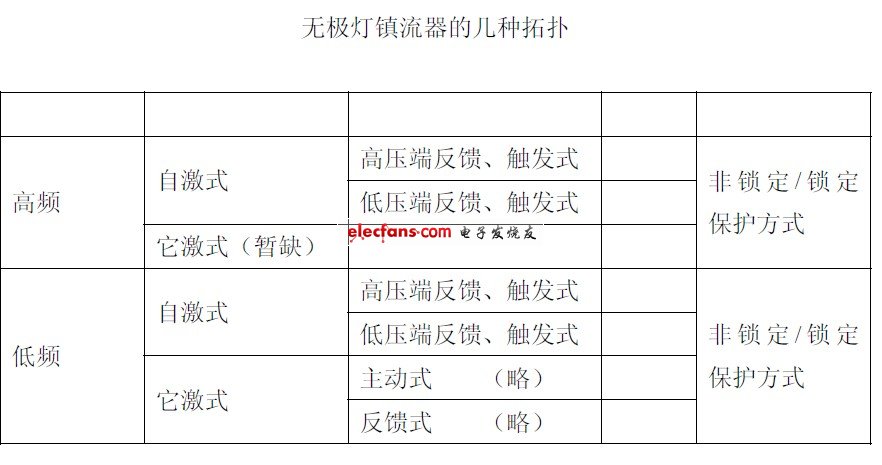
introduction This article refers to the address: http:// The electrodeless lamp is the abbreviation of Promise Light (electrodeless lamp) high-frequency electromagnetic plasma discharge lamp, which consists of three parts: bulb/tube, coupler (inside and outside), and electronic ballast (high and low frequency). The ballast acts as a frequency converter and drives, the coupler (electromagnetic converter) and the bulb/tube are the load of the ballast. These lamps have a very long life and can reach more than 60,000 to 100,000 hours. The electrodeless ballast is a high-frequency (180-250KHz; 2-3MHz) AC-type electrical energy required to convert the grid power of 85V~265V 50Hz/60Hz into a high-reliability and high-efficiency to drive the bulb/tube. The characteristics of the bulb/tube determine the technology and material guarantee that the life of the whole system depends mainly on the high reliability, high stability of the operating life of the high frequency electronic ballast.    1 bulb/tube characteristics of induction lamps 1.1 Negative resistance characteristics That is, the equivalent impedance of the lamp rises with the rise of the temperature T, and the impedance decreases. If the ballast has an infinite flow function, the lamp power will continuously rise until the circuit or the lamp is damaged.    1.2 Startup characteristics At startup, voltages of up to several thousand volts and sufficient power are required to achieve the equivalent equivalent impedance of the lamp gas from high resistance to operation (analysis of the operation of the lamp from electrical characteristics).    1.3 Temperature characteristics That is, the difference in ambient temperature makes the initial equivalent impedance values ​​of the lamps vary greatly, and this feature has a significant effect on the startup of the lamp at low temperatures.    2 bulb / tube and drive power supply As with the conventional fluorescent tube/HID method, an inductor is connected in series with the power supply. The inductor is a ballast inductor or a choke inductor. The principle of the inductor stabilizing the load current is a negative feedback regulation. In the case of ordinary power frequency, in order to achieve the required inductance of the ballast, the volume is large and the weight is heavy. In order to reduce the volume and weight, the operating frequency is increased, thus introducing a frequency converter, which is an energy-saving lamp and a poleless Lamp electronic ballast. Due to the frequency conversion and the improvement of the power factor, the electromagnetic interference problem is brought about, and the circuit has to be added to solve the electromagnetic interference. To achieve the ballast, the circuit is complicated and huge. Start-up problem, ordinary fluorescent lamp / HID start is to use the ballast inductor reverse surge voltage and power supply voltage superposition to achieve high-voltage start. The electrodeless lamp electronic ballast uses the resonance principle to generate high voltage to achieve startup. In addition to the high voltage requirement at startup, another important parameter is power. Only when the starting current reaches the bulb/tube starting power requirement can the bulb/tube be activated effectively. The third characteristic of the bulb/tube is that the initial equivalent impedance of the lamp is greatly increased due to the temperature drop, so that the starting current is relatively reduced under the same resonance voltage, which affects the start of the lamp, which makes starting difficult. In addition, the proper cooperation of the electrodeless lamp and the lamp ensures a good heat dissipation effect, and is also an important part of giving full play to the excellent performance of the electrodeless lamp.    3 key research issues of ballast ballast technology 3.1 Energy efficiency Efficiency problems in the frequency conversion process The efficiency of the ballast directly affects whether the electrodeless lamp is energy efficient. In the study of solving the efficiency problem, I believe that under the principle of ensuring the normal and safe operation of the circuit, when designing the circuit: First, it is necessary to reduce the circuit as much as possible; second, it is necessary to optimize all parameters of the system (to eliminate the short-board effect) ), and take the first principle of reducing consumption, cost considerations are second. The components in the ballast circuit are all physical components. As long as the work inevitably produces losses, the properties of the different components are different. They can be divided into two categories: one is a fixed loss class, such as a diode, a resistor, or a wire. Wait. The parameters of such components are simple to design, and only need to select some components according to the circuit principle, power, withstand voltage and other basic parameters to achieve the lowest energy loss circuit design. The second category is variable loss class, such as FET (transistor), capacitor, and inductor. The parameter design of such components is the key to reducing consumption. The designed power consumption is low, and the design power is greatly increased. The design must consider not only the parameters of individual components, but also the overall optimization of the circuit, which is a very systematic work. When using a FET as a switch, the drive performance is an important factor affecting the power consumption of the field tube. Some circuits are usually designed to ensure the rising and falling rates of the drive waveform, making the waveform steep. For example, an acceleration circuit when turned on, a stored charge when turned off, and the like. Testing some manufacturers' products, found such a phenomenon, some ballast waveforms are good, but the power consumption is still large, the field tube temperature is also high, there is a burning tube phenomenon; some product waveforms are general, power consumption Not as bad as expected, the temperature is not too high, and the failure phenomenon is not obvious. If you only analyze from the driver, you can't explain this phenomenon. However, the theoretical analysis of the drive, circuit, load characteristics, power supply, and combined circuit, that is, system parameter optimization (to eliminate the short-board effect), proves the rationality of this phenomenon. In the design and production of the ballast, the parameters of each part are calculated and adjusted according to the optimized circuit model, so that the power consumption of the product itself is reduced, and the reliability and stability are improved. Generally only consider the needs of the circuit function, and less effort to reduce the consumption. These components only exchange energy in the theoretical state and consume little energy. However, due to the difference of parameter design, material selection and manufacturing process, the energy consumption is far different, and this is the high-power electrodeless lamp ballast. Design and production is worthy of a thorough study of all manufacturers.    3.2 Harmonic interference Electromagnetic Compatibility and Harmonic Suppression Problems In addition to the fundamental wave, the input currents containing various distortions also contain a wealth of higher harmonic components. These excessive harmonic components can seriously affect the public power grid, thus forming harmonic interference. . This periodic spike current is narrower, which makes the DC ripple voltage fluctuate and makes the peak coefficient of the lamp current larger, which is extremely disadvantageous for the bulb/tube. Similarly, the luminous flux of the lamp is also increased, which causes great damage to human vision. When the DC ripple voltage fluctuates and becomes large, the switch tube can not be in the optimal working state, and it is easy to generate heat and cause damage, and the service life of the ballast will be greatly shortened, which is not worth the loss. An improvement to suppress harmonics is to increase their power factor as much as possible and reduce the harmonic distortion of the input current. To achieve this goal, it is necessary to increase the conduction rate of the rectifier (ie, extend the conduction time of the input current), so that the waveform of the power supply current is close to the sine wave of the voltage, reducing the waveform distortion of the current; at the same time, ensuring the power supply filter capacitor It can smoothly supply power continuously to the load (ie, reduce the phase difference between the input current and the input voltage). This is what is commonly referred to as the power factor correction circuit. The power correction circuit is divided into passive correction (PPFC) and active correction (APFC). At present, the low-power integrated electrodeless lamp electronic ballast products are limited to cost and price factors, and most of them adopt passive passivation circuits composed of improved flow-by-flow circuits. This technology has developed relatively maturely. As long as the debugging is done properly, the harmonic content of the ballast can be effectively suppressed, and the power factor can reach 0.85-0.90. However, such a circuit has difficulty in debugging, and it is difficult to control the quality of the product in mass production, and basically cannot meet the requirements of electromagnetic compatibility standards and performance standards at the same time. The active correction is a harmonic suppression circuit composed of discrete active devices such as a triode, or a harmonic suppression circuit using an ASIC, and the power factor can generally reach 0.95-0.99 or more. And the latter debugging is simpler than the former, and the reliability is higher. Electromagnetic induction of induction lamps is mainly radiated interference and conducted interference. Radiated interference points to space to emit electromagnetic waves, also called radio frequency interference. Conducted interference refers to interference to the power grid; it mainly comes from power factor correction, variable frequency output, circuit coupling, etc. local. Due to the extremely high operating frequency of the electrodeless lamp and the large output power, the hard switching characteristics of the power tube during the switching process will generate a large number of odd harmonics and even harmonic interference. Relatively speaking, the frequency conversion output (ballast operating frequency) The interference accounts for the majority. What is reflected in the EMC detection is that the interference near the operating frequency and its multiple frequency increases significantly. As the ballast power increases, the interference intensity increases. For this problem, it must be from the input stage. Corresponding processing is performed on the filter circuit, the power factor correction circuit, and the resonance circuit. The PCB design, process, and structure of high-frequency circuits are critical to EMC. The location, routing, grounding, and heat dissipation of important components must be carefully analyzed and carefully placed. After analyzing a large amount of data for conducting and radiating tests on electronic ballasts, it is known that the electromagnetic interference generated by electronic ballast products mainly dominates the differential mode interference in the frequency range of 9~150KHz; the frequency range of 150KHz~30MHz Mainly due to common mode interference. Finding the source of the interference and knowing the cause of the interference, only need to take corresponding measures to suppress the interference, so that it is not difficult to pass the assessment of the clause. In addition to the string EMI filter at the input (power supply) of the ballast, it is also possible to work on the components that cause interference in the ballast. From the previous analysis, it is known that the switching tube generates a higher amplitude pulse voltage or current at the moment of its on and off. As long as the pulse voltage or current is eliminated or weakened, the interference voltage of the ballast can be reduced. A ceramic capacitor can be respectively connected between the base and the emitter of the switch tube to reduce the deep saturation of the transistor, which helps to reduce the amplitude of the pulse voltage, and also prevents the common state of the switch from being turned on, so as not to damage the switch tube. Or add a damping network (D, R, C) between the collector and emitter of the switch tube to absorb the inrush current generated between the switch, protect the switch tube, and effectively reduce the interference intensity.    3.3 Working frequency The parameter design of the resonant circuit is composed of a ballast inductor, a coupled inductor, a resonant capacitor, etc., which generates a resonant voltage when energized. After the lamp is turned on, the ballast inductor and the coupler form a stable voltage distribution relationship. The factors to be considered in the circuit design are the operating frequency, resonant frequency, power control, resonant voltage and other parameters within a reasonable range. The operating frequency of the electrodeless ballast is currently 2.65MHz (self-excited shock drive) and 250KHz (it is driven by shock), generally a fixed frequency. When the frequency, bulb/tube power is determined, the design parameters are pushed forward by the bulb/tube power. When designing the resonance parameters, the lamp can be set to an open state, and the ballast inductance, the coupler inductance, and the capacitance form a series-parallel (LCC) circuit. Where f0 is the resonant frequency, L1 is the ballast inductance, L2 is the coupled inductor, and C2 is the resonant capacitor. Usually, L1 and L2 are basically equal. According to the lamp power, lamp temperature, etc., the coupler wire diameter, number of turns, magnetic ring parameters, and inductance can be determined. The coupler is similar to the bulb/tube transformer. The primary is the coupler and the secondary is the bulb/tube. The secondary current will change the primary inductance, causing the resonant circuit parameters to change, f0 offset, and the ballast at a constant frequency. Working in an inductive load state (ie, the output frequency is slightly higher than the drive frequency). The negative feedback of the ballast inductor regulates the bulb/tube power. Appropriately increase the resonant voltage and feedback voltage amplitude to facilitate sufficient margin during low temperature startup.    4 abnormal situation protection There are several main aspects to protect the abnormal condition of the protection of the electrodeless lamp under abnormal conditions: high temperature protection, over voltage protection, protection during work, and start protection. Since the electronic ballast of the electrodeless lamp is an electronic component, the service life of the capacitive component is greatly reduced when the ballast is operated for more than 70 degrees for a long time. Therefore, a high temperature protection circuit must be provided in the work to ensure the ballast. Life and stability. In abnormal situations such as lightning strikes, the grid supply voltage will generate a very short time high voltage surge. If there is no effective circuit to derive this instantaneous energy out of the circuit, it will cause permanent damage to the ballast, according to the surge level. Different, you need to set the protection circuit of different strength. Protection during work refers to the protection of the abnormal situation of the tube rupture, air leakage and power surge after the lamp is normally lit. In this abnormal situation, if the protection circuit reacts too long or there is no protection, the ballast Will be damaged in a very short time. Start-up protection refers to the protection of the circuit when the lamp fails due to air leakage, low temperature, etc., when the circuit is in a capacitive or weak state. This protection is critical. Most of the induction lamp damage is caused by this phenomenon. In this case, multiple protection measures must be taken according to different situations. The abnormal protection of the electrodeless lamp is generally divided into two modes: non-locking and locking. In the protection process, the switch tube is still in the working state, and the protection state is continuously started. If the protection state is long, it is easy to cause the power switch tube or the protection switch. Damage to the tube. The locking switch of the locking mode does not work during the protection process, and the circuit supports the protection state for a certain period of time (the national standard requires more than 50 seconds), and the power switch is restarted.    5 Conclusion Analysis of these steps of the electrodeless lamp, it can be seen that the technical problems to be solved by the electrodeless lamp ballast are: frequency conversion, high conversion efficiency, EMC filtering, resonant circuit design, protection under abnormal conditions and so on.
JoyLED indoor fine pitch Led Display adopting positioning pins to achieve structural installation, fast and reliable. Built-in lock system in the LED display cabinet, seamless splicing and assembling.
Avoiding transmission failures caused by traditional signal connectors and flat wire. Failure rate decreases by 60%.
Real-time monitoring on operating status.
Automatic fault diagnosis, positioning and warning of failures.
Die-casting aluminum LED cabinet,360° convection ventilation design.
Intelligent control and player system by cloud technology.
Timely managing real-time information on operating status and potential failure.
3D/2D freely switching, without additional devices.
Indoor Fine Pitch Led Display,Led Fine Pitch Display,Fine Pixel Pitch Led Display,Fine Pitch Commercial Led Display Shenzhen Joy LED Display Co., Ltd. , https://www.joe-led.com