Must-have, three DIY small speaker solutions to choose from
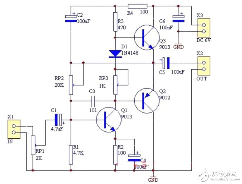
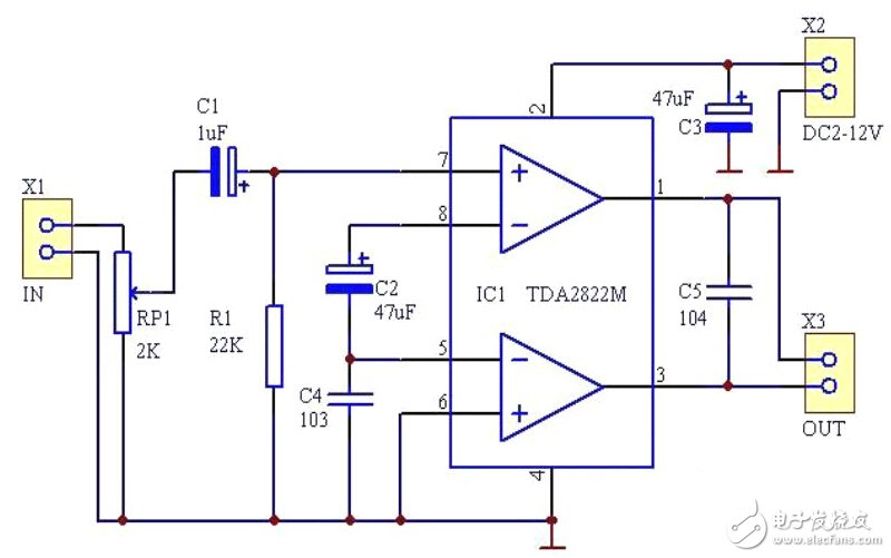
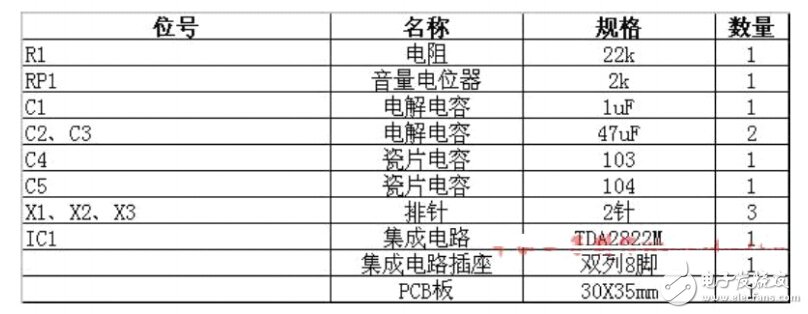
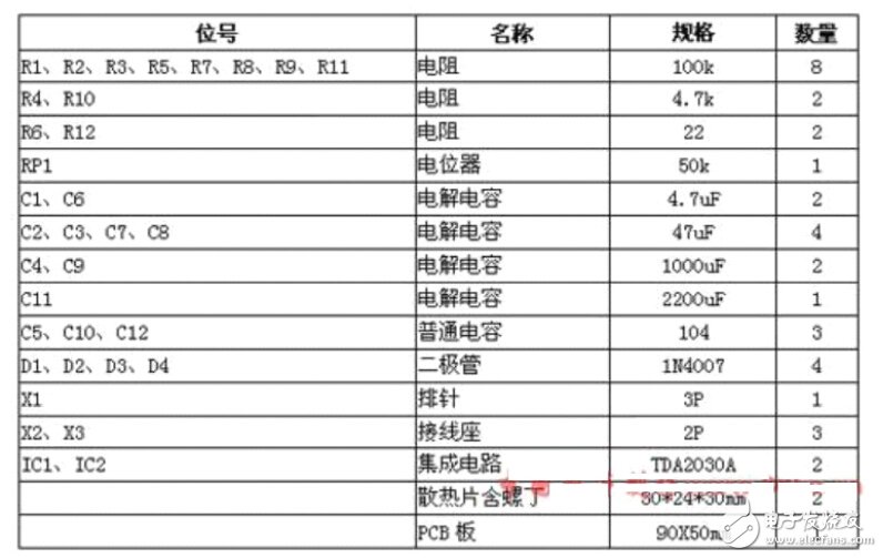
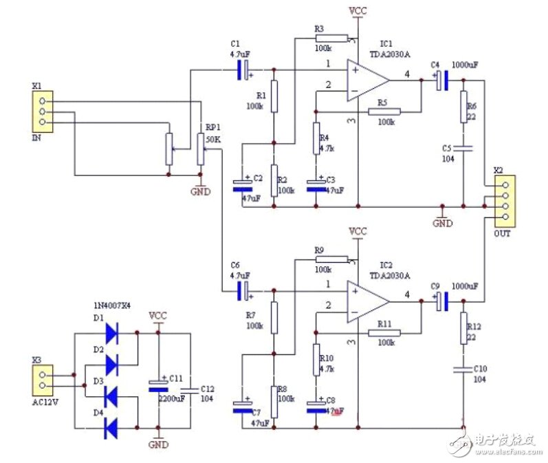
Homemade small speaker (1) First, the circuit description Q1 is the excitation amplifier tube, which gives the power amplifier output stage enough push signal; R1, RP2 is the bias resistor of Q1; R3, D1, RP3 are connected in series on the Q1 collector circuit to provide bias for Q3 , making it statically in micro-conduction state to eliminate crossover distortion; C3 is anti-vibration capacitor for eliminating self-excitation caused by circuit; Q2, Q3 are complementary symmetric push-pull power amplifier tubes, composing power amplification output stage ; C2, R4 constitute the "bootstrap circuit", R4 is the current limiting resistor. Second, the circuit debugging is connected to the 3-6V DC power supply, adjust RP2, make the Q2, Q3 midpoint voltage is 1/2 power supply voltage; adjust RP3, make the power amplifier output stage quiescent current 5-8mA; repeatedly adjust RP2, RP3 to make it Both parameters reach the above values. This amplifier kit is synchronized with the electronic basic course materials and is suitable for students to use internships. Third, the component list Fourth, the circuit schematic The following contents are: OTL discrete component power amplifier kit welding process 1. Check the number of components according to the component list, and confirm that there is no error before soldering. 2, welding resistors and diodes 3, welding two adjustable resistors 4, welding terminal block 5, welding triode 6, welding electrolytic capacitors and ceramic capacitors, the shadow part of the electrolytic capacitor symbol on the circuit board is the negative pole, pay attention to the welding 7. Finally, solder the volume potentiometer. Here, the OTL discrete component power amplifier kit is soldered. Homemade small speaker (2) The TDA2822M is a dual-channel monolithic power amplifier integrated circuit developed by STMicroelectronics for portable recording and playback equipment. It features low crossover distortion and low quiescent current for stereo and bridge amplification (BTL). Another unique feature of the TDA2822M is its wide operating voltage range, which works well in the 2V-12V range, but unless it is used in a headphone amplifier, it is best to let the TDA2822M operate above 3V. This circuit is connected to a single bridge-type amplification (BTL) by a TDA2822M power amplifier integrated circuit. There are few external components, no heat sink, and the playback effect is satisfactory. Second, the parameter power supply voltage: 2V-12V Output power: 2W (1KHz, 8Ω, 9V, 10% total distortion) Static current: ≤9mA (Vcc=3V) Harmonic distortion: 0.2% (1kHz, 8Ω~32Ω) Closed loop gain : 39dB (typ.) Load range: ≥4Ω Third, the circuit schematic Fourth, the list of components The following is: 2822 Mono Power Amplifier Kit Welding Process 1. Check the number of components according to the component list 2, first solder small components such as ceramic capacitors and resistor pins 3, soldering integrated circuit sockets, pay attention not to reverse when soldering 4, welding electrolytic capacitor, electrolytic capacitor has positive and negative, the longer end of the pin is positive 5, solder the volume potentiometer, install the key component of the 2822 mono power amplifier TDA2822M, the welding is completed Homemade small speaker (3) (two channels) I. Circuit Description: This kit is a power amplifier composed of integrated circuit TDA2030A. It has the characteristics of small distortion, few external components, simple assembly, high power and high fidelity. It is very suitable for radio enthusiasts and audiophiles. Assembly. In the circuit, D1—D4 are rectifier diodes, C11 is filter capacitor, C12 is high frequency decoupling capacitor; RP1 is volume adjustment potentiometer; IC1 and IC2 are two channel power amplifier integrated circuits; R1, R2, R3, C2 ( R7, R8, R9, C7) is the bias circuit of the input end of the power amplifier IC. Since this circuit is powered by a single power supply, the circuit can work normally when the DC voltage of the input terminal of the power amplifier IC is 1/2 power supply voltage; R4, R5, C3 (R10) , R11, C8) constitute a negative feedback loop, changing the size of R4 (R10) can change the feedback coefficient. C1 (C6) is the input coupling capacitor, C4 (C9) is the output coupling capacitor; R6, C5 (R12, C10) ensure high frequency stability when the circuit is connected with an inductive load speaker. Signal flow: The audio signal is input from X1 via volume potentiometer RP1, then coupled by C1 (C6), enters pin 1 of IC1 (IC2), is amplified by integrated circuit and output from pin 4, and reaches through output coupling capacitor C4 (C9). X2. Second, the performance parameters Input voltage: AC≤15V Output power: Po=5W+5W (RL=4Ω) Output impedance: 4-8 Ω Third, the component list Fourth, the circuit schematic The following is: 2030 two-channel power amplifier kit welding process 1. Look at the component list to see if there is any error in the number of component names. It is best to measure each component and verify that it is correct. 2, first solder resistance and diode 3, welding signal input pin 4, soldering terminal block, signal output terminal block to tie two terminal blocks together and then solder 5, welding electrolytic capacitors and monolithic capacitors, monolithic capacitors are non-polar, electrolytic capacitors have polarity, the shaded part of the circuit board is the negative pole of the capacitor 6, welding power supply filter capacitor and output coupling capacitor, these three capacitors should pay attention to its polarity, reversed may cause capacitor overheating burst 7, welding volume potentiometer, the outer casing of the potentiometer should be connected to a "grounding" line, as shown in the figure, when welding this wire, use a steel shovel to polish the outer potentiometer shell, so that the welding is firm 8, the effect of the "grounding" line on the potentiometer after welding 9. Finally solder the heat sink and TDA2030A, so the 2030 two-channel power amplifier kit is soldered. The start-up battery is the soul of your vehicle. It starts the Engine, and generates the energy necessary for the operation of all other vehicle's electric aspects. But did you know that it only has two years of life approximately? Since during the unloading process and float charging, the battery's negative plate is sulphated fast, Reducing the functional capacity of the battery, until its complete inoperative. That's why we present the start-up Battery Pulse Protector. We offer you a fully automatic battery maintainer and protection system, it works 24 hours a day. Battery protector is not a battery charger. It is a patented electronic Sulfuric Crystal Cleaner which will eliminate the battery sulphation which is the main cause of problems and failures in lead acid start-up batteries. This battery pulse desulfator keeps the battery's condition as new, provides faster starts up your car or truck. Extends battery lifespan up to two or more times and reduce recharge time. Increase the capacity for your charge to last longer between recharges. Helps to protect the environments because it reduce the number of batteries that are discarded every year. Start-up Battery Protector,Start-up Solar Battery Protector,Start Up Battery Regenerator,Car Battery Intelligent Protector Shenzhen Daceen Technology Co., Ltd. , https://www.daceen-sz.com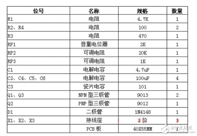
How is it installed? Lugs connect directly to the battery terminals.
Designed especially for frequently-charged 12-Volt battery systems, the 12V Battery smart pulse protector and pulse maintainer ensures maximum performance on both single 12-Volt lead-acid batteries as well as two or three 12-Volt batteries connected in parallel. The battery pulse protector is ideal for any kind of vehicle or UPS with a 12-Volt battery system that is charged on a regular basis, including cars,trucks, ships, emergency vehicles,military battery backup power and vehicles in sudden war,wind and solar power battery, motor, UPS.