How to use an external analog voltage to control a digital potentiometer
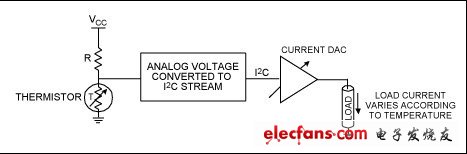
This application note describes an easy way to change the resistance of a digital potentiometer using an external analog voltage. The analog voltage is converted to an I2C data stream that controls the digital potentiometer using Microchip's PIC12F683 microcontroller. The digital potentiometer DS1803 is used as an example device in this application, and a very small number of other external devices are used. The method described here is applicable to other controller inputs and other digital potentiometers/variable resistors. Hardware Configuration Figure 1 shows the schematic of the control circuit using the PIC12F683. Four of the six GPIOs of the microcontroller are used to control the SDA, SCL output signals, a single LED, and receive an analog input. GP5, GP4, and GP0 are assigned to the signal outputs SDA, SCL, and LED, respectively. SDA and SCL have a 4.7kΩ pull-up resistor to VDD and are directly connected to the SDA and SCL pins of the DS1803. The GP1 IO of the microcontroller is assigned as an analog input pin. The address pins can be selected by jumpers, the shared VCC (VDD) can be separated, and the SDA and SCL can be isolated. Figure 1. Schematic of an analog voltage controlled digital potentiometer Engineering firmware The firmware of this project is written in assembly language in the MPLAB IDE (version 7.40) environment. This compilation tool is currently available free of charge from Microchip. All programs occupy less than 450 bytes of program space (Flash) and 8 bytes of data space (RAM). The program first initializes multiple configuration bits of the PIC, including the ADC and the internal oscillator. The program configures the ADC to input from GP1 and sets the conversion clock to use the internal 125kHz oscillator. The firmware runs a loop: the ADC continuously converts the voltage at the analog input. Once the conversion is complete, the upper 8 bits of the 10-bit ADC output are passed as data bytes to the I2C bus. This I2C signal is used to control the DS1803. The program is set to control the two potentiometers of the DS1803 together; however, by changing the firmware, two digital potentiometers can be independently controlled by the two different analog inputs of the PIC12F683. A variety of functions The program allows the user to control the digital potentiometer by changing the voltage at the PIC12F683 GP1 input. A continuous change in the voltage at the GP1 terminal causes a corresponding change in the digital potentiometer resistance. The output resistance (ROUT) can be thought of as a function of the input voltage. The DS1803 end-to-end resistance used in the design is: 50kΩ VCC allowable range: 2.7V to 5V Input voltage varies from 0V to VCC The output resistance will follow: ROUT (kΩ) = (50/VCC (kΩ)) &TImes; input voltage The LED keeps flashing while the ADC is running. If the I2C fails, the LED remains lit. Once the fault is removed, the LED continues to operate normally. The designer can troubleshoot the system by checking that the device address is correct and the I2C bus is connected. This design is very versatile and a similar approach can be used in multiple systems. Some examples include: Nonlinear transfer functions (eg, gamma calibration) can be implemented using the variable resistor DS3906 in conjunction with the appropriate transfer function stored in the embedded lookup table. When the ambient temperature changes, a thermistor can be connected to the input to change the I2C controlled current mode DAC (DS4402/DS4404). in conclusion This application note describes an easy and low-cost method of using an analog voltage to control a digital potentiometer. The method in this application can be extended to use analog voltage to control any device with an I2C interface.
Fahold Electronics Co.,ltd redefine the art of indoor lighting, providing the high efficiency and Flicker Free Led Driver for led lighting, office lighting and hospitality lighting. For high bay and low bay industrial lighting and warehouse lighting power source, choose Fahold drivers
Features:
Input voltage: 100-240vac
What's the benefits of Fahold Driver?
TUV Plastic Case AC100-240V Led Driver 48V Switching Power Supply,Constant Current Driver 40W,30 Watt Led Downlight,panel light. ShenZhen Fahold Electronic Limited , https://www.fahold.com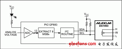
output voltage: 25-40vdc / 27-42vdc / 35-45vdc / 50-70vdc / 12Vdc / 24vdc
current: 100mA-1500mA.
Power factor: >0.9
Dimming:0-10V / PWM / RX
>=50000hours, 3 years warranty.
certificate: TUV CE CB
 .
.